 |
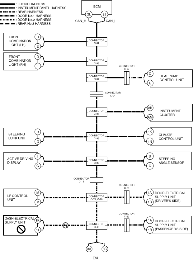
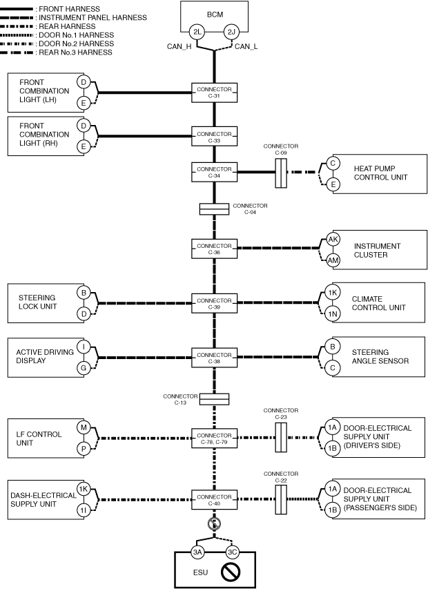
a30zzw00006561
DETERMINING OPEN CIRCUIT LOCATION (CAN-BUS No.3) [R.H.D.]
id100226002500
1. Verify the CAN system-related module DTCs and the module displayed in red or blue on the M-MDS screen.
2. Apply the communication error DTC and the module displayed in red or blue to the DTC output pattern and malfunctioning location, and select the possible cause for the diagnostic result and the reference for the inspection item. (See DTC Output Pattern And Malfunctioning Location)
3. Inspect the possible cause and inspection item of the applicable malfunctioning part.
DTC Output Pattern And Malfunctioning Location
|
M-MDS display |
DTC |
DTC output pattern and malfunctioning location |
||||||||||||||||||||
|---|---|---|---|---|---|---|---|---|---|---|---|---|---|---|---|---|---|---|---|---|---|---|
|
DTC output module |
||||||||||||||||||||||
|
PCM (e-SKYACTIV)
|
U0100:00
|
|||||||||||||||||||||
|
U0103:00
|
||||||||||||||||||||||
|
U0121:00
|
||||||||||||||||||||||
|
U0129:00
|
||||||||||||||||||||||
|
U0131:00
|
||||||||||||||||||||||
|
U0140:00
|
×
|
|||||||||||||||||||||
|
U0151:00
|
||||||||||||||||||||||
|
U0155:00
|
×
|
×
|
×
|
×
|
×
|
|||||||||||||||||
|
U0156:00
|
||||||||||||||||||||||
|
U0164:00
|
×
|
×
|
×
|
×
|
×
|
×
|
×
|
×
|
×
|
|||||||||||||
|
U016B:00
|
×
|
×
|
×
|
×
|
||||||||||||||||||
|
U01BA:00
|
||||||||||||||||||||||
|
U0291:00
|
||||||||||||||||||||||
|
U102D:00
|
||||||||||||||||||||||
|
U2121:00
|
||||||||||||||||||||||
|
U212E:00
|
×
|
×
|
×
|
×
|
×
|
×
|
×
|
×
|
||||||||||||||
|
U2131:00
|
×
|
×
|
×
|
×
|
×
|
×
|
×
|
×
|
×
|
|||||||||||||
|
U2133:00
|
×
|
×
|
×
|
×
|
×
|
×
|
||||||||||||||||
|
Parking lock actuator
|
U0100:00
|
|
|
|
|
|
|
|
|
|
|
|
|
|
|
|
|
|
|
|
|
|
|
U0115:00
|
|
|
|
|
|
|
|
|
|
|
|
|
|
|
|
|
|
|
|
|
|
|
|
U0100:41
|
|
|
|
|
|
|
|
|
|
|
|
|
|
|
|
|
|
|
|
|
|
|
|
U0100:82
|
|
|
|
|
|
|
|
|
|
|
|
|
|
|
|
|
|
|
|
|
|
|
|
Electronically controlled brake unit
|
U0100:00
|
|||||||||||||||||||||
|
U0131:00
|
||||||||||||||||||||||
|
U0140:00
|
×
|
|||||||||||||||||||||
|
U0151:00
|
||||||||||||||||||||||
|
U0155:00
|
×
|
×
|
×
|
×
|
×
|
|||||||||||||||||
|
U0164:00
|
×
|
×
|
×
|
×
|
×
|
×
|
×
|
×
|
×
|
|||||||||||||
|
U2121:00
|
||||||||||||||||||||||
|
U212E:00
|
×
|
×
|
×
|
×
|
×
|
×
|
×
|
×
|
||||||||||||||
|
U2131:00
|
×
|
×
|
×
|
×
|
×
|
×
|
×
|
×
|
×
|
|||||||||||||
|
SAS control module
|
U0140:00
|
×
|
||||||||||||||||||||
|
U0155:00
|
×
|
×
|
|
×
|
|
×
|
|
×
|
||||||||||||||
|
U0155:41
|
×
|
×
|
|
×
|
|
×
|
|
×
|
||||||||||||||
|
U0155:82
|
|
|
|
|
|
|
|
|
|
|
×
|
×
|
|
×
|
|
×
|
|
×
|
||||
|
U0156:00
|
|
|
|
|
|
|
|
|
|
|
×
|
×
|
|
×
|
|
×
|
|
×
|
||||
|
U0156:41
|
|
|
|
|
|
|
|
|
|
|
×
|
×
|
|
×
|
|
×
|
|
×
|
||||
|
U0156:82
|
|
|
|
|
|
|
|
|
|
|
×
|
×
|
|
×
|
|
×
|
|
×
|
||||
|
Auto leveling control module
|
U0122:87
|
|||||||||||||||||||||
|
U212A:87
|
×
|
×
|
||||||||||||||||||||
|
U212B:87
|
×
|
|||||||||||||||||||||
|
U212D:87
|
×
|
×
|
×
|
|||||||||||||||||||
|
Adaptive LED headlights control module
|
U0122:87
|
|||||||||||||||||||||
|
U0126:87
|
×
|
×
|
×
|
×
|
×
|
×
|
×
|
|||||||||||||||
|
U0155:87
|
×
|
×
|
×
|
×
|
×
|
|||||||||||||||||
|
U2121:87
|
||||||||||||||||||||||
|
U212A:87
|
×
|
×
|
||||||||||||||||||||
|
U212B:87
|
×
|
|||||||||||||||||||||
|
U212D:87
|
×
|
×
|
×
|
|||||||||||||||||||
|
Selector lever
|
U0100:00
|
|
|
|
|
|
|
|
|
|
|
|
|
|
|
|
|
|
|
|
|
|
|
U0121:00
|
|
|
|
|
|
|
|
|
|
|
|
|
|
|
|
|
|
|
|
|
|
|
|
U0140:00
|
|
|
|
|
|
|
|
|
|
|
|
|
|
|
|
|
|
|
|
|
×
|
|
|
U212B:00
|
|
|
|
|
|
|
|
|
|
|
|
|
|
|
|
|
|
|
|
|
×
|
|
|
EPS control module
|
U0100:00
|
|
|
|
|
|
|
|
|
|
|
|
|
|
|
|
|
|
|
|
|
|
|
U0121:00
|
|
|
|
|
|
|
|
|
|
|
|
|
|
|
|
|
|
|
|
|
||
|
U0140:00
|
|
|
|
|
|
|
|
|
|
|
|
|
|
|
|
|
|
|
|
×
|
||
|
U2121:00
|
|
|
|
|
|
|
|
|
|
|
|
|
|
|
|
|
|
|
|
×
|
||
|
Vehicle control module (VCM)
|
U0100:00
|
|||||||||||||||||||||
|
U0101:00
|
||||||||||||||||||||||
|
U0121:00
|
||||||||||||||||||||||
|
U0126:00
|
×
|
×
|
×
|
×
|
×
|
×
|
×
|
|||||||||||||||
|
U0131:00
|
||||||||||||||||||||||
|
U0140:00
|
×
|
|||||||||||||||||||||
|
U0151:00
|
||||||||||||||||||||||
|
U0155:00
|
×
|
×
|
×
|
×
|
×
|
|||||||||||||||||
|
U0156:00
|
||||||||||||||||||||||
|
U0164:00
|
×
|
×
|
×
|
×
|
×
|
×
|
×
|
×
|
×
|
|||||||||||||
|
U2120:00
|
||||||||||||||||||||||
|
U2122:00
|
||||||||||||||||||||||
|
U2123:00
|
||||||||||||||||||||||
|
U2125:00
|
||||||||||||||||||||||
|
U2126:00
|
|
|||||||||||||||||||||
|
U212E:00
|
×
|
×
|
×
|
×
|
×
|
×
|
×
|
×
|
||||||||||||||
|
U2131:00
|
×
|
×
|
×
|
×
|
×
|
×
|
×
|
×
|
×
|
|||||||||||||
|
U2132:00
|
||||||||||||||||||||||
|
U2133:00
|
×
|
×
|
×
|
×
|
×
|
×
|
||||||||||||||||
|
U2139:00
|
||||||||||||||||||||||
|
U213A:00
|
×
|
×
|
×
|
×
|
×
|
×
|
×
|
×
|
×
|
|||||||||||||
|
Body control module (BCM)
|
U0100:00
|
|||||||||||||||||||||
|
U0101:00
|
||||||||||||||||||||||
|
U0103:00
|
||||||||||||||||||||||
|
U0103:87
|
||||||||||||||||||||||
|
U0111:00
|
||||||||||||||||||||||
|
U0115:00
|
||||||||||||||||||||||
|
U0121:00
|
||||||||||||||||||||||
|
U0121:87
|
||||||||||||||||||||||
|
U0126:00
|
×
|
×
|
×
|
×
|
×
|
×
|
×
|
|||||||||||||||
|
U0131:00
|
||||||||||||||||||||||
|
U0151:00
|
||||||||||||||||||||||
|
U0155:00
|
×
|
×
|
×
|
×
|
×
|
|||||||||||||||||
|
U0156:00
|
||||||||||||||||||||||
|
U0158:00
|
×
|
×
|
×
|
×
|
×
|
×
|
×
|
|||||||||||||||
|
U0164:00
|
×
|
×
|
×
|
×
|
×
|
×
|
×
|
×
|
×
|
|||||||||||||
|
U016B:00
|
×
|
×
|
×
|
×
|
||||||||||||||||||
|
U0182:00
|
||||||||||||||||||||||
|
U0198:00
|
||||||||||||||||||||||
|
U01BA:00
|
||||||||||||||||||||||
|
U2121:49
|
||||||||||||||||||||||
|
U212A:00
|
×
|
|||||||||||||||||||||
|
U212D:00
|
×
|
|||||||||||||||||||||
|
U212E:00
|
×
|
×
|
×
|
×
|
×
|
×
|
×
|
×
|
||||||||||||||
|
U2131:00
|
×
|
×
|
×
|
×
|
×
|
×
|
×
|
×
|
×
|
|||||||||||||
|
U2133:00
|
×
|
×
|
×
|
×
|
×
|
×
|
||||||||||||||||
|
U2135:00
|
||||||||||||||||||||||
|
U213A:00
|
×
|
×
|
×
|
×
|
×
|
×
|
×
|
×
|
×
|
|||||||||||||
|
U213B:00
|
×
|
×
|
×
|
×
|
×
|
×
|
×
|
×
|
||||||||||||||
|
U213C:00
|
||||||||||||||||||||||
|
U2147:00
|
||||||||||||||||||||||
|
Dash-electrical supply unit
|
U0100:00
|
|||||||||||||||||||||
|
U0121:00
|
||||||||||||||||||||||
|
U0140:00
|
×
|
|||||||||||||||||||||
|
U0151:00
|
||||||||||||||||||||||
|
U0156:00
|
||||||||||||||||||||||
|
U016B:00
|
×
|
|||||||||||||||||||||
|
U212E:00
|
×
|
|||||||||||||||||||||
|
U2131:00
|
×
|
|||||||||||||||||||||
|
U2133:00
|
×
|
|||||||||||||||||||||
|
U213A:00
|
×
|
|||||||||||||||||||||
|
Heat pump control unit
|
U2133:00
|
×
|
×
|
×
|
×
|
×
|
×
|
|||||||||||||||
|
U0140:00
|
×
|
|||||||||||||||||||||
|
U0164:00
|
×
|
×
|
×
|
×
|
×
|
×
|
||||||||||||||||
|
Connectivity master unit (CMU)
|
U0101:00
|
|||||||||||||||||||||
|
U0131:00
|
||||||||||||||||||||||
|
U0140:00
|
×
|
|||||||||||||||||||||
|
U0151:00
|
||||||||||||||||||||||
|
U0155:00
|
×
|
×
|
×
|
×
|
×
|
|||||||||||||||||
|
U0198:00
|
||||||||||||||||||||||
|
U2121:00
|
||||||||||||||||||||||
|
U213C:00
|
||||||||||||||||||||||
|
U213E:00
|
||||||||||||||||||||||
|
Emergency call unit
|
U0140:00
|
×
|
||||||||||||||||||||
|
U0151:00
|
||||||||||||||||||||||
|
U0164:00
|
×
|
×
|
×
|
×
|
×
|
×
|
×
|
×
|
×
|
|||||||||||||
|
U213C:00
|
||||||||||||||||||||||
|
Approaching vehicle audible system device
|
U0101:00
|
|
||||||||||||||||||||
|
U0121:00
|
|
|||||||||||||||||||||
|
M-MDS display module
|
Module displayed in red or blue
|
|||||||||||||||||||||
|
Electrical supply unit (ESU)
|
×
|
×
|
×
|
×
|
×
|
×
|
×
|
×
|
×
|
|||||||||||||
|
Dash-electrical supply unit
|
×
|
×
|
×
|
×
|
×
|
×
|
×
|
×
|
×
|
|||||||||||||
|
Door-electrical supply unit (passenger's side)
|
×
|
×
|
×
|
×
|
×
|
×
|
×
|
×
|
×
|
|||||||||||||
|
LF control unit
|
×
|
×
|
×
|
×
|
×
|
×
|
×
|
×
|
||||||||||||||
|
Door-electrical supply unit (driver's side)
|
×
|
×
|
×
|
×
|
×
|
×
|
×
|
×
|
||||||||||||||
|
Steering angle sensor
|
×
|
×
|
×
|
×
|
×
|
×
|
×
|
|||||||||||||||
|
Active driving display
|
×
|
×
|
×
|
×
|
×
|
×
|
×
|
|||||||||||||||
|
Climate control unit
|
×
|
×
|
×
|
×
|
×
|
×
|
||||||||||||||||
|
Steering lock unit
|
×
|
×
|
×
|
×
|
×
|
×
|
||||||||||||||||
|
Instrument cluster
|
×
|
×
|
×
|
×
|
×
|
|||||||||||||||||
|
Heat pump control unit
|
×
|
×
|
×
|
×
|
||||||||||||||||||
|
Front combination light (RH)
|
×
|
×
|
×
|
|||||||||||||||||||
|
Front combination light (LH)
|
×
|
×
|
||||||||||||||||||||
|
Diagnostic result
|
||||||||||||||||||||||
|
Possible cause and inspection item
|
||||||||||||||||||||||
A
Possible cause
System wiring diagram
a30zzw00006561
|
Inspection item
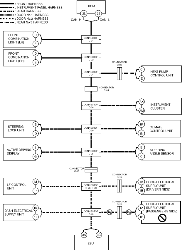
B
Possible cause
System wiring diagram
a30zzw00006562
|
Inspection item
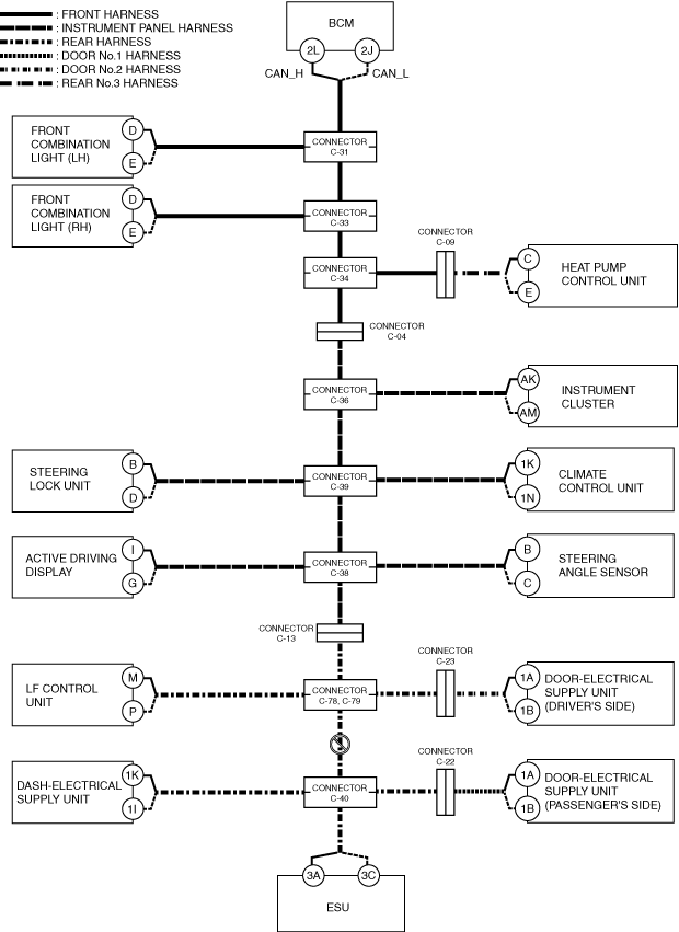
C
Possible cause
System wiring diagram
a30zzw00006563
|
Inspection item
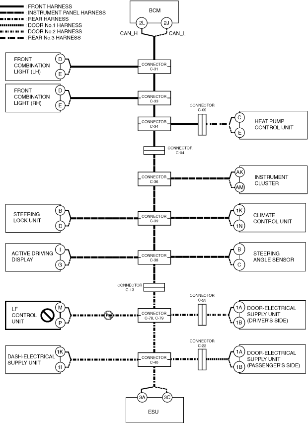
D
Possible cause
System wiring diagram
a30zzw00006564
|
Inspection item
E
Possible cause
System wiring diagram
a30zzw00006565
|
Inspection item
F
Possible cause
System wiring diagram
a30zzw00006566
|
Inspection item
G
Possible cause
System wiring diagram
a30zzw00006567
|
Inspection item
H
Possible cause
System wiring diagram
a30zzw00006568
|
Inspection item
I
Possible cause
System wiring diagram
a30zzw00006569
|
Inspection item
J
Possible cause
System wiring diagram
a30zzw00006570
|
Inspection item
K
Possible cause
System wiring diagram
a30zzw00006571
|
Inspection item
L
Possible cause
System wiring diagram
a30zzw00006572
|
Inspection item
M
Possible cause
System wiring diagram
a30zzw00006573
|
Inspection item
N
Possible cause
System wiring diagram
a30zzw00006574
|
Inspection item
O
Possible cause
System wiring diagram
a30zzw00006575
|
Inspection item
P
Possible cause
System wiring diagram
a30zzw00006576
|
Inspection item
Q
Possible cause
System wiring diagram
a30zzw00006577
|
Inspection item
R
Possible cause
System wiring diagram
a30zzw00006578
|
Inspection item
S
Possible cause
System wiring diagram
a30zzw00006579
|
Inspection item
T
Possible cause
System wiring diagram
a30zzw00006580
|
Inspection item
U
Possible cause
System wiring diagram
a30zzw00006581
|
Inspection item