CRUISING & TRAFFIC SUPPORT (CTS) [(E)]
id1510000045a4
Outline
• The cruising & traffic support (CTS) is a system to reduce driving fatigue during long drives on expressways and it consists of the headway control function and the steering assist function.
• When the front radar sensor and the forward sensing camera (FSC) detect target information while driving in constant speed control mode, they send target information to the body control module (BCM) and switch to headway control mode.
• Using the headway control function allows the driver to maintain constant-speed driving at a set vehicle speed and to maintain a constant distance from a vehicle ahead without having to depress the accelerator or brake pedal.
• If the detecting vehicle stops when the vehicle ahead stops, headway control resumes after the vehicle ahead moves again.
-
Warning
-
• Do not rely completely on the cruising & traffic support (CTS) and always drive carefully. There are limitations to the distance between the vehicles which can be controlled by the cruising & traffic support (CTS), and if the accelerator pedal or brake pedal is mistakenly operated it could result in an accident. Always keep a safe distance from the vehicle ahead by depressing the brake pedal if necessary while verifying the safety of the surrounding area.
• The cruising & traffic support (CTS) performs brake control, however, there are limitations to the deceleration, and the system may be unable to decelerate sufficiently to avoid hitting the vehicle ahead if the vehicle ahead applies the brakes suddenly or another vehicle cuts into the driving lane, which could result in an accident. Always keep a safe distance from the vehicle ahead by depressing the brake pedal if necessary while verifying the safety of the surrounding area.
• The cruising & traffic support (CTS) is not a system for the purpose of autonomous driving. In all situations, always make it your responsibility as a driver to check the vehicle's surroundings and drive the vehicle correctly.
• The cruising & traffic support (CTS) functions have limitations. Over reliance on the cruising & traffic support (CTS) and neglecting prudent steering wheel operation could cause an unexpected accident resulting in death or serious injury. Do not rely completely on the cruising & traffic support (CTS). Always stay on course using the steering wheel and drive carefully.
-
Caution
-
• If the forward sensing camera (FSC) aiming is not completed correctly, the forward sensing camera (FSC) cannot record the camera shooting angle and the cruising & traffic support (CTS) may not operate normally. When performing the following servicing, always perform the forward sensing camera (FSC) aiming. For the forward sensing camera (FSC) aiming procedure, refer to [FORWARD SENSING CAMERA (FSC) AIMING] in the workshop manual.
-
― Forward sensing camera (FSC) replacement
― Windshield replacement
• If the front radar sensor aiming is not completed correctly, the front radar sensor cannot record angle corrections and the cruising & traffic support (CTS) may not operate normally. When performing the following servicing, always perform the front radar sensor aiming. For the front radar sensor aiming procedure, refer to [FRONT RADAR SENSOR AIMING] in the workshop manual.
-
― Front radar sensor replacement
― Front bumper replacement
― Mascot replacement
-
Note
-
• The headway control does not detect the following objects as target objects.
-
― On-coming vehicles
-
― Pedestrians
-
― Stationary objects (such as stopped vehicles, obstructions)
• If a vehicle ahead is driving extremely slowly, it could not be detected correctly.
• If there are road structures or obstructions (such as a monorail) at a low position from the ground ahead, the system could operate. Therefore, do not use the CTS.
• Do not use the CTS under conditions in which proximity warnings activate frequently.
• When acceleration is required such as when making a lane change, or when suddenly approaching a vehicle such as the vehicle ahead suddenly applies the brakes, accelerate using the accelerator pedal or decelerate using the brake pedal according to the conditions.
• When deceleration is required, reduce the set vehicle speed or depress the brake pedal.
• While the brakes are operating under CTS control, an operation sound may be heard, however it does not indicate a malfunction.
• While the brakes are operating under CTS control, the brake lights turn on, however they may not turn on while traveling at a set speed on a downslope or following a vehicle ahead at a constant speed.
• Under the following conditions, the CTS may not operate normally if it cannot detect white lines (yellow lines) of the vehicle lane or a vehicle ahead.
-
― Forward sensing camera (FSC) cannot recognize white lines (yellow lines) and vehicles ahead due to dirty or fogged windshield
-
― Poor white line (yellow line) visibility due to fading or soiling
-
― Poor white line (yellow line) or vehicle ahead visibility due to weather (such as rain, fog, or snow)
-
― Vehicle is driven on temporary lane or section with closed lane resulting from construction (there might be multiple white lines (yellow lines) or they are interrupted)
-
― Indiscernible white lines (yellow lines), road maintenance markings, shadows, residual snow, or water-filled road ruts are visible.
-
― Road surface is wet and shiny or there are water puddles after rainfall
-
― Vehicle is tilted by heavy cargo in luggage compartment or rear seat
-
― Poor white line (yellow line) visibility due to vehicle ahead traveling near white lines (yellow lines)
-
― Windshield is dirty or fogged
-
― Vehicle is driven through intersection, junction, or on forked road
-
― White lines (yellow lines) of vehicle lane cannot be detected due to road conditions or weather
-
― Surrounding brightness suddenly changes such as when entering or exiting tunnel
-
― At night, headlight lens is dirty and illumination is weak or its optical axis is deviated
-
― Road surface is shiny due to backlight or after rainfall
-
― Shadow of guardrail parallel to white lines (yellow lines) is cast on road
-
― Width of driving lane lines is narrow or wide
-
― Vehicle is driven on winding road
-
― Vehicle is shaken after hitting road bump
-
― There are various road markings or lane markings of various shapes near intersection
-
― There is dirt in front of the camera or something obstructing the view is attached
-
― Smoke from vehicle exhaust, sand, snow, steam rising from manholes or grating, or water spray is dispersed into air
-
― Dim light such as at evening and early morning
-
― Vehicle ahead has taillights with special shape
-
― Vehicle ahead is traveling largely deviated from center of detecting vehicle
-
― Vehicle ahead is traveling erratically
-
― Sharp curves
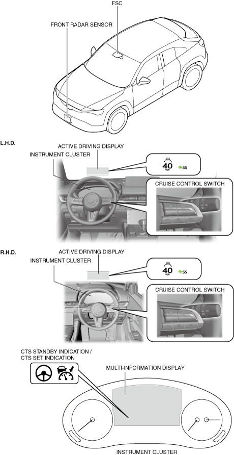
Structural view
Function
• The cruising & traffic support (CTS) has the following functions.
-
― Headway control function: When a vehicle ahead is detected while the vehicle is traveling in constant speed control mode, headway control with the vehicle ahead is performed while maintaining the set vehicle speed and the set distance between the vehicles by the driver. In addition, the detecting vehicle stops when the vehicle ahead stops, and headway control mode/constant speed control mode is resumed by operating the RES switch/accelerator pedal after the vehicle ahead moves again.
― Steering assist function: When vehicle lane lines are detected while driving, the function assists the driver’s steering wheel operation to keep the vehicle within the driving lane. When vehicle lane lines are not being detected, the function assists the driver’s steering operation to follow the trajectory of the vehicle ahead.
― Hands off steering wheel detection function: If the driver takes his/her hands off the steering wheel while driving, a warning is displayed on the multi-information display and the active driving display to warn the driver. If driver’s hands remain off the steering wheel, the system turns off.
― Stop hold function : If the vehicle ahead stops while following the vehicle ahead, the function stops the detecting vehicle at the previously set distance between vehicles and maintains a stopped condition.
Status transition
-
• Cruising & traffic support (CTS) switch operation (standby status)
When the cruising & traffic support (CTS) switch of the cruise control switch is pressed, the cruising & traffic support (CTS) standby indication (white) and the Mazda radar cruise control (MRCC) standby indication (white) on the multi-information display and the active driving display turn on.
-
Note
-
• The CTS operates when the cruising & traffic support (CTS) switch is pressed while the Mazda radar cruise control (MRCC) or the Mazda Radar Cruise Control with Stop & Go function (MRCC with Stop & Go function) is operating.
• SET+/Set- switch operation (constant speed control)
Constant speed control begins when the desired vehicle speed is adjusted using the accelerator pedal and the SET+ or SET- switch of the cruise control switch is pressed. The set vehicle speed is displayed on the multi-information display and the active driving display. At the same time, the indication changes from the Mazda radar cruise control (MRCC) standby indication (white) to the set indication (green).
• Vehicle ahead detection (headway control)
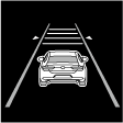
Headway control begin when the front radar sensor and the forward sensing camera (FSC) detect a vehicle ahead while traveling at a constant speed. At the same time, the vehicle ahead indication is displayed on the multi-information display and the active driving display.
• Driving lane trace
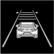
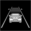
When the forward sensing camera (FSC) detects the driving lane and the operation conditions are met, the indication changes from the cruising & traffic support (CTS) standby indication (white) to the set indication (green), the vehicle lane lines (white) are displayed on the multi-information display, and the system assists the driver’s steering wheel operation to remain the vehicle near the center of the driving lane.
• Vehicle ahead trajectory tracking (headway control)
If the driving lane is not detected, the trajectory of the vehicle ahead is tracked and the indication changes from the cruising & traffic support (CTS) standby indication (white) to the set indication (green).
• Vehicle ahead not detected (constant speed control)
When the vehicle ahead no longer appears, the vehicle ahead indication on the multi-information display and the active driving display turns off and the system switches to constant speed control.
• Cruising & traffic support (CTS) switch operation (operation stop)
When the CTS switch is pressed while the cruising & traffic support (CTS) is operating, the CTS operation stops and the cruising & traffic support (CTS) standby indication (white) or the set indication (green) turns off.
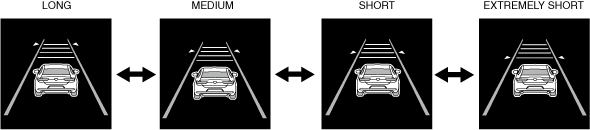
Distance between vehicles setting function
-
• Using the DISTANCE switch on the cruise control switch, the distance between vehicles during headway control mode can be controlled at 4 levels, including longÆmediumÆshortÆextremely short. (Initial setting is LONG)
-
Caution
-
• The distances between vehicles indicated below are average values during travel on flat roads and differ depending on the driving and road conditions.
Distance between vehicles table (reference)
|
Set distance between vehicles
|
Monitoring vehicle speed
|
|
0 km/h
{0 mph}
|
10 km/h
{6.2 mph}
|
20 km/h
{12 mph}
|
30 km/h
{19 mph}
|
40 km/h
{25 mph}
|
50 km/h
{31 mph}
|
60 km/h
{37 mph}
|
|
Long
|
5 m
{17 ft}
|
11 m
{37 ft}
|
18 m
(60 ft)
|
24 m
{79 ft}
|
30 m
{99 ft}
|
37 m
{122 ft}
|
43 m
{142 ft}
|
|
Medium
|
5 m
{17 ft}
|
10 m
{33 ft}
|
15 m
{50 ft}
|
20 m
{66 ft}
|
26 m
{86 ft}
|
31 m
{102 ft}
|
36 m
{119 ft}
|
|
Short
|
5 m
{17 ft}
|
10 m
{33 ft}
|
15 m
{50 ft}
|
18 m
{60 ft}
|
22 m
{73 ft}
|
25 m
{83 ft}
|
29 m
{96 ft}
|
|
Extremely short
|
5 m
{17 ft}
|
10 m
{33 ft}
|
15 m
{50 ft}
|
17 m
{56 ft}
|
19 m
{63 ft}
|
22 m
{73 ft}
|
24 m
{79 ft}
|
|
Set distance between vehicles
|
Monitoring vehicle speed
|
|
70 km/h
{43 mph}
|
80 km/h
{50 mph}
|
90 km/h
{56 mph}
|
100 km/h
{62 mph}
|
110 km/h
{68 mph}
|
120 km/h
{75 mph}
|
130 km/h
{81 mph}
|
140 km/h
{87 mph}
|
|
Long
|
49 m
{161 ft}
|
56 m
{184 ft}
|
62 m
{204 ft}
|
68 m
{224 ft}
|
75 m
{247 ft}
|
81 m
{266 ft}
|
87 m
{286 ft}
|
94 m
{309 ft}
|
|
Medium
|
41 m
{135 ft}
|
46 m
{150 ft}
|
51 m
{168 ft}
|
56 m
{184 ft}
|
62 m
{204 ft}
|
67 m
{220 ft}
|
72 m
{237 ft}
|
77 m
{253 ft}
|
|
Short
|
32 m
{105 ft}
|
35 m
{115 ft}
|
39 m
{128 ft}
|
42 m
{138 ft}
|
46 m
{151 ft}
|
49 m
{161 ft}
|
52 m
{171 ft}
|
56 m
{184 ft}
|
|
Extremely short
|
26 m
{86 ft}
|
28 m
{92 ft}
|
31 m
{102 ft}
|
33 m
{109 ft}
|
35 m
{115 ft}
|
37 m
{122 ft}
|
39 m
{128 ft}
|
42 m
{138 ft}
|
System conditions display
• The body control module (BCM) displays the system conditions on the active driving display, multi-information display, and the center display.
|
Condition
|
CTS standby indication
|
CTS set indication
|
i-ACTIVSENSE warning indication
|
Multi-information display indication (Instrument cluster)
|
Active driving display indication
|
|
CTS system is OFF
|
Off
|
Off
|
Off
|
No display
|
No display
|
|
CTS system is ON
|
CTS system is on standby
|
On
|
Off
|
Off
|
 |
 |
|
Vehicle ahead is detected
|
Off
|
On
|
Off
|
 |
 |
|
Distance between vehicles
|
Long
|
Off
|
On
|
Off
|
 |
 |
|
Medium
|
Off
|
On
|
Off
|
 |
 |
|
Short
|
Off
|
On
|
Off
|
 |
 |
|
Extremely short
|
Off
|
On
|
Off
|
 |
 |
|
Driver takes his or her handsoff steering wheel
|
Off
|
On
|
Off
|
 |
 |
|
CTS system is ON
|
Accelerator pedal is depressed
|
On
|
Off
|
Off
|
No display
|
No display
|
|
Deceleration exceeding system limits required
|
Off
|
On
|
Off
|
 |
No display
|
|
CTS system temporarily off due to related unit condition
|
Off
|
Off
|
On
|
 |
No display
|
|
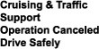
CTS system off without driver’s intention
|
Off
|
Off
|
Off
|
 |
 |
|
Malfunction occurred in CTS system
|
Off
|
Off
|
On
|
 |
No display
|
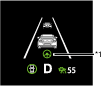
*1 :When the steering assist function operates, the steering assist operation display on the display changes from white to green.
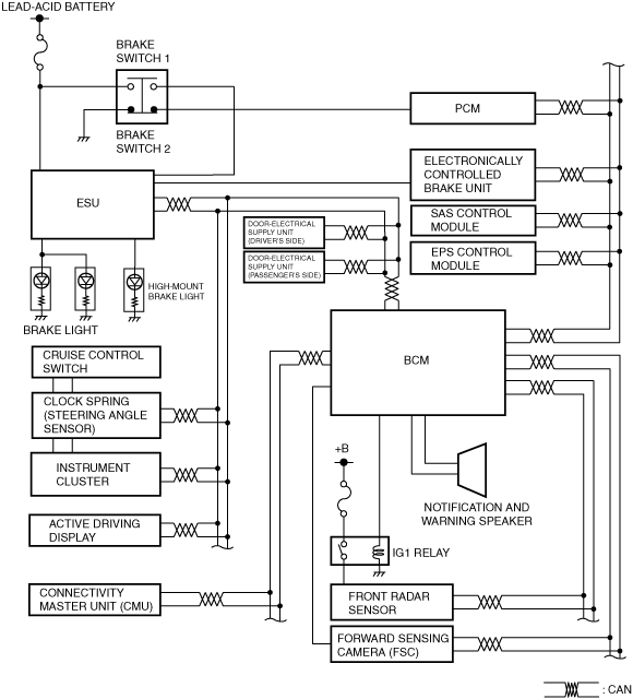
System wiring diagram
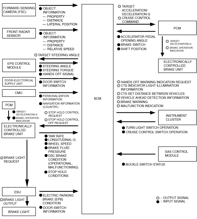
Block diagram
Operation
• For details on autohold, refer to [AUTOHOLD]. (See
AUTOHOLD.)
• When all of the following conditions are met, the Cruising & Traffic Support (CTS) operates.
Operation condition
-
― Vehicle speed is within range of approx. 0 km/h {0 mph} to 145 km/h {90mph}
― Selector lever is in D position
-
Note
-
• Under the following conditions, the CTS cannot be used when the vehicle speed is less than approx. 30 km/h {20 mph}. In addition, a message, “Mazda Radar Cruise Control Disabled Under 30 km/h (20 mph)“ is displayed in the multi-information display.
-
― The forward sensing camera (FSC) cannot detect target objects (windshield is damaged or dirty).
― The CTS may not launch directly after the main power ON (READY on).
― The Cruising & Traffic Support (CTS) is operation
― The headway control function of the Mazda Radar Cruise Control (MRCC) or Mazda Radar Cruise Control with Stop & Go function (MRCC with Stop & Go function) is set to operable (if it was set to inoperable, set it to operable using the personalization function)
― The brake pedal is not depressed
― The parking brake is released (Electric Parking Brake (EPB) indicator light is turned off)
― All the doors are closed
― The driver’s seat belt is fastened
-
Note
-
• The steering assist function operates under the following conditions.
-
― Vehicle speed is less than approx. 55 km/h {34 mph}.
― White (yellow) lane lines on both sides are detected and you are driving near the center of the lane, or your vehicle detects a vehicle ahead.
― The steering wheel is not turned sharply.
― The turn signal lever is not operated.
― The headway control function is operating.
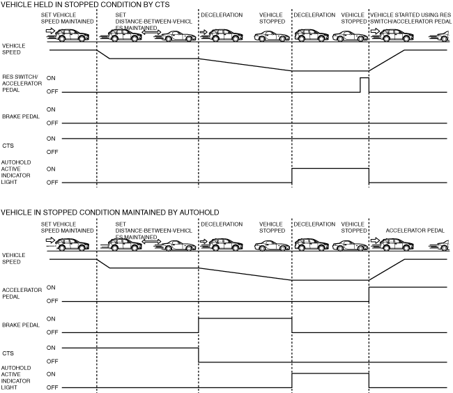
Headway control function
-
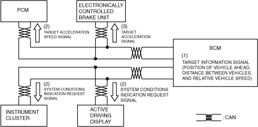
1. When the front radar sensor and the forward sensing camera (FSC) detect target information while driving in constant speed control mode, they send the target information to the body control module (BCM).
2. The body control module (BCM) calculates the target acceleration/deceleration speed based on the following, and sends a target acceleration/deceleration speed signal to the PCM and the electronically controlled brake unit. In addition, it sends a system status indication request signal to the instrument cluster and the active driving display.
-
― Distance between vehicles set by driver
― Target information (position, speed of vehicle ahead)
― Vehicle speed
3. The PCM controls the drive force to maintain the distance between vehicles based on the target acceleration/deceleration speed signal from the body control module (BCM).
4. The electronically controlled brake unit controls the brakes to maintain the distance between vehicles based on the target acceleration/deceleration speed signal from the body control module (BCM).
5. The instrument cluster displays the vehicle ahead screen on the multi-information display based on the system status indication signal from the body control module (BCM).
6. The active driving display displays the vehicle ahead screen based on the system status indication request signal from the body control module (BCM).
-
Note
-
• In the following cases, the system transitions from headway control mode to constant speed mode.
-
― Vehicle ahead accelerates over set vehicle speed of detecting vehicle
― Vehicle ahead or detecting vehicle switches driving lanes, and vehicle ahead of detecting vehicle no longer exists
-
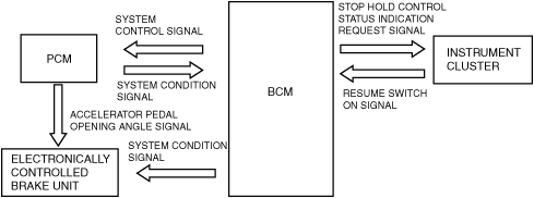
Stop hold control
-
1. If the vehicle ahead stops during headway control mode, the front radar sensor and the forward sensing camera (FSC) send target information to the body control module (BCM), and the body control module (BCM) sends a system control signal to the PCM and the electronically controlled brake unit to stop the vehicle at the previously set distance between vehicles.
2. The PCM controls the drive force and stops the vehicle based on the system control signal from the body control module (BCM).
3. The electronically controlled brake unit performs brake control to stop the vehicle and maintain it in a stopped condition based on the system control signal from the body control module (BCM).
4. The body control module (BCM) sends an AUTOHOLD operation indicator light request signal to the instrument cluster after the vehicle stops.
5. The instrument cluster turns on the AUTOHOLD operation indicator light based on the AUTOHOLD operation indicator light request signal from the body control module (BCM).
6. After the body control module (BCM) recognizes that the vehicle ahead has accelerated forward during stop hold control, the PCM and the electronically controlled brake unit cancel stop hold control when they receive the following signals.
-
― Accelerator pedal opening angle signal (accelerator pedal depressed) from PCM
― RES switch ON signal (RES switch pressed) from instrument cluster
-
Note
-
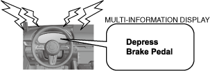
• After the vehicle ahead accelerates forward and a certain period of time has elapsed, the vehicle ahead indication on the multi-information display flashes to promote the driver to accelerate the vehicle.
• While in stop hold control, the electrical supply unit (ESU) turns on the brake lights.
• When 10 min or more have elapsed since stop hold control was operated, the electric parking brake operates and the Mazda Radar Cruise Control with Stop & Go function (MRCC with Stop & Go function) goes on stand-by.
7. The body control module (BCM) sends a system control signal to the PCM and the electronically controlled brake unit to resume headway control mode/constant speed control mode.
Steering assist function
-
1. The front radar sensor and the forward sensing camera (FSC) send target information to the body control module (BCM). In addition, when the forward sensing camera (FSC) detects the driving lane, it sends driving lane information to the body control module (BCM).
2. The body control module (BCM) calculates the target steering angle based on the following and it sends a target steering angle signal to the electric power steering (EPS) control module.
-
― Target information (position, speed of vehicle ahead)
― Vehicle speed, acceleration speed, steering angle, yaw rate
― Driving lane information
3. The body control module (BCM) sends a system status indication request signal to the instrument cluster and the active driving display.
4. The EPS control module keeps the vehicle in the driving lane or controls the steering wheel so that it tracks the trajectory of the vehicle ahead based on the target steering angle signal from the body control module (BCM).
5. The instrument cluster displays the system status on the multi-information display based on the system status indication request signal from the body control module (BCM).
6. The active driving display displays the system status based on the system status indication request signal from the body control module (BCM).
Hands off warning function
-
1. When the EPS control module detects the driver release the hands from the steering wheel, it sends the hands off judgement signal to the body control module (BCM).
2. When the body control module (BCM) receive the hands off signal from the EPS control module, it sends the hands off judgement signal to the instrument cluster and the active driving display. In addition, it outputs the warning signal to the front speaker.
3. The instrument cluster display the warning information on the multi-information display based on the hands off judgement signal from the body control module (BCM).
4. The active driving display display the warning information based on the hands off judgement signal from the body control module (BCM).
Inter-vehicle distance limit warning
-
• If any of the following conditions is met, the warning alarm from the instrument cluster is activated and a brake warning is displayed on the display to urge the driver to apply the brakes.
-
― The body control module (BCM) determines that crash is unavoidable even if automatic braking is performed at maximum possible deceleration rate such as a vehicle ahead performs emergency braking.