 |
am3zzw00027438
REAR SIDE RADAR SENSOR INSPECTION
id152000020900
1. Disconnect the negative lead-acid battery terminal. (See NEGATIVE LEAD-ACID BATTERY TERMINAL DISCONNECTION/CONNECTION.)
2. Remove the rear side radar sensor. (See REAR SIDE RADAR SENSOR REMOVAL/INSTALLATION.)
3. Connect the rear side radar sensor connector.
4. Connect the negative lead-acid battery terminal. (See NEGATIVE LEAD-ACID BATTERY TERMINAL DISCONNECTION/CONNECTION.)
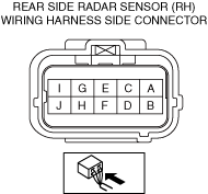
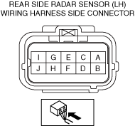
5. Verify that the voltages of each of the terminals are as indicated in the terminal voltage table (reference).
Terminal Voltage Table (Reference)
Rear side radar sensor (LH)
am3zzw00027438
|
|
Terminal |
Signal name |
Connected to |
Measurement conditions |
Voltage (V) |
Inspection item(s) |
|
|---|---|---|---|---|---|---|
|
A
|
PRI_CAN_H
|
Front side radar sensor (RH)
|
Because this terminal is for communication, determination using terminal voltage inspection is not possible.
|
|||
|
B
|
PRI_CAN_L
|
Front side radar sensor (RH)
|
Because this terminal is for communication, determination using terminal voltage inspection is not possible.
|
|||
|
C
|
—
|
—
|
—
|
—
|
—
|
|
|
D
|
—
|
—
|
—
|
—
|
—
|
|
|
E
|
—
|
—
|
—
|
—
|
—
|
|
|
F
|
—
|
—
|
—
|
—
|
—
|
|
|
G
|
—
|
—
|
—
|
—
|
—
|
|
|
H
|
—
|
—
|
—
|
—
|
—
|
|
|
I
|
Power position (IG1)
|
IG1 relay No.1
|
Main power is switched ON (READY off or on)
|
VB
|
• F54 10A fuse
• IG1 relay No.1
• Related wiring harness
|
|
|
Main power is switched OFF or ACC
|
1.0 or less
|
|||||
|
J
|
Ground
|
Body ground
|
Under any condition
|
Approx. 0
|
• GND point
• Related wiring harness
|
|
Rear side radar sensor (RH)
am3zzw00027437
|
|
Terminal |
Signal name |
Connected to |
Measurement conditions |
Voltage (V) |
Inspection item(s) |
|
|---|---|---|---|---|---|---|
|
A
|
PRI_CAN_H
|
Front side radar sensor (RH)
|
Because this terminal is for communication, determination using terminal voltage inspection is not possible.
|
|||
|
B
|
PRI_CAN_L
|
Front side radar sensor (RH)
|
Because this terminal is for communication, determination using terminal voltage inspection is not possible.
|
|||
|
C
|
ADAS_CAN_H
|
Data link connector-2
|
Because this terminal is for communication, determination using terminal voltage inspection is not possible.
|
|||
|
D
|
ADAS_CAN_L
|
Data link connector-2
|
Because this terminal is for communication, determination using terminal voltage inspection is not possible.
|
|||
|
E
|
—
|
—
|
—
|
—
|
—
|
|
|
F
|
—
|
—
|
—
|
—
|
—
|
|
|
G
|
—
|
—
|
—
|
—
|
—
|
|
|
H
|
—
|
—
|
—
|
—
|
—
|
|
|
I
|
Power position (IG1)
|
IG1 relay No.1
|
Main power is switched ON (READY off or on)
|
VB
|
• F54 10A fuse
• IG1 relay No.1
• Related wiring harness
|
|
|
Main power is switched OFF or ACC
|
1.0 or less
|
|||||
|
J
|
Ground
|
Body ground
|
Under any condition
|
Approx. 0
|
• GND point
• Related wiring harness
|
|