 |
a30zzn00000991
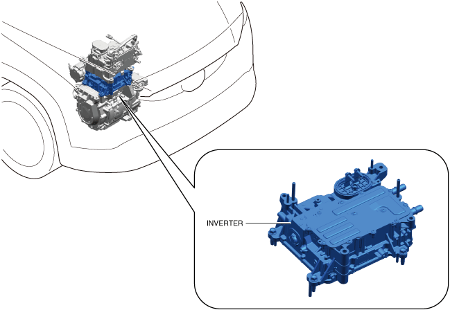
ELECTRIC DRIVE SYSTEM CONTROL
id301000200600
Drive Motor Control Module
Outline
a30zzn00000991
|
|
Part name |
Content |
|---|---|
|
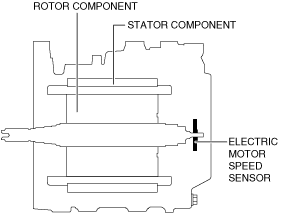
Electric motor speed sensor
|
Detects the motor rotation angle and rotation direction. (See Electric Motor Speed Sensor.)
|
|
Electric motor temperature sensor
|
Detects the electric motor temperature and inputs signals which vary according to the electric motor temperature to the drive motor control module.
|
|
Electric motor current sensor
|
Detects electrical current in the U phase, V phase, and W phase in the electric motor and inputs the information to the drive motor control module.
|
|
Input voltage sensor
|
Detects the voltage to be input to the inverter from the high voltage battery and inputs the information to the drive motor control module.
|
|
Power transistor temperature sensor
|
Detects the power transistor temperatures at the U phase, V phase, and W phase in the inverter and inputs the information to the driver motor control module.
|
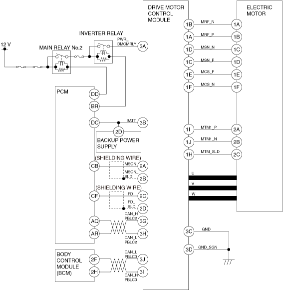
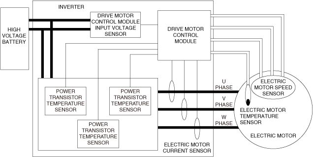
Construction
a30zzn00000992
|
System wiring diagram
a30zzn00001176
|
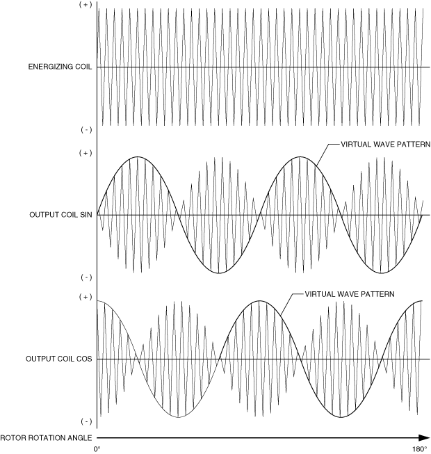
Electric Motor Speed Sensor
Purpose, Function
Construction
a30zzn00000994
|
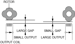
Operation
a30zzn00000888
|
a30zzn00001164
|