 |
a30zzw00003966
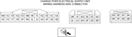
CHARGE PORT-ELECTRICAL SUPPLY UNIT INSPECTION
id304000102300
Charge Port-Electrical Supply Unit Terminal Table (Reference)
a30zzw00003966
|
|
Terminal |
Signal name |
Connection |
Measured item |
Measurement condition |
Voltage (V) |
Inspection items |
|
|---|---|---|---|---|---|---|---|
|
1A
|
—
|
—
|
—
|
—
|
—
|
—
|
|
|
1B
|
—
|
—
|
—
|
—
|
—
|
—
|
|
|
1C
|
CAN_H_PBLC
|
CAN system-related unit
|
—
|
Because this terminal is for communication, examination using terminal voltage is not possible.
|
|||
|
1D
|
—
|
—
|
—
|
—
|
—
|
—
|
|
|
1E
|
—
|
—
|
—
|
—
|
—
|
—
|
|
|
1F
|
CAN_L_PBLC
|
CAN system-related unit
|
—
|
Because this terminal is for communication, examination using terminal voltage is not possible.
|
|||
|
1G
|
BATT
|
Lead-acid battery
|
Voltage
|
Continuous
|
B+
|
• Related wiring harness
|
|
|
1H
|
—
|
—
|
—
|
—
|
—
|
—
|
|
|
1I
|
IG1
|
IG1 relay No.2
|
Voltage
|
Main power is switched ON (READY off or on)
|
B+
|
• IG1 relay
• Related wiring harness
|
|
|
Conditions other than above
|
1.0 or less
|
||||||
|
1J
|
BATT2
|
Lead-acid battery
|
Voltage
|
Continuous
|
B+
|
• Related wiring harness
|
|
|
1K
|
—
|
—
|
—
|
—
|
—
|
—
|
|
|
1L
|
—
|
—
|
—
|
—
|
—
|
—
|
|
|
1M
|
GND_SIG
|
Body ground
|
Voltage
|
Continuous
|
0.5 or less
|
• Ground point
• Related wiring harness
|
|
|
1N
|
—
|
—
|
—
|
—
|
—
|
—
|
|
|
1O
|
—
|
—
|
—
|
—
|
—
|
—
|
|
|
1P
|
GND
|
Body ground
|
Voltage
|
Continuous
|
0.5 or less
|
• Ground point
• Related wiring harness
|
|
|
1Q
|
—
|
—
|
—
|
—
|
—
|
—
|
|
|
1R
|
—
|
—
|
—
|
—
|
—
|
—
|
|
|
1S
|
—
|
—
|
—
|
—
|
—
|
—
|
|
|
1T
|
—
|
—
|
—
|
—
|
—
|
—
|
|
|
1U
|
—
|
—
|
—
|
—
|
—
|
—
|
|
|
1V
|
—
|
—
|
—
|
—
|
—
|
—
|
|
|
1W
|
—
|
—
|
—
|
—
|
—
|
—
|
|
|
1X
|
—
|
—
|
—
|
—
|
—
|
—
|
|
|
2A
|
LID_LOCK_N
|
Charge lid lock actuator
|
Voltage
|
Charge lid is locked
|
1.0 or less*2
|
• Charge lid lock actuator
• Related wiring harness
|
|
|
Charge lid is unlocked
|
B+ changes to 1.0 or less*1
|
||||||
|
2B
|
LID_LOCK_P
|
Charge lid lock actuator
|
Voltage
|
Charge lid is locked
|
B+ changes to 1.0 or less*1
|
• Charge lid lock actuator
• Related wiring harness
|
|
|
Charge lid is unlocked
|
1.0 or less*2
|
||||||
|
2C
|
CHARGE_IND_VSUP
|
Charge indicator
|
Voltage
|
Main power is switched ON (READY off)
|
B+
|
• Charge indicator
• Related wiring harness
|
|
|
Conditions other than above
|
1.0 or less
|
||||||
|
2D
|
CP_LAMP_VSUP
|
Charge port illumination (Built-in charge indicator)
|
Voltage
|
Main power is switched ON (READY off)
|
B+
|
• Charge indicator
• Related wiring harness
|
|
|
Conditions other than above
|
1.0 or less
|
||||||
|
2E
|
CHARGE_IND_W
|
Charge indicator
|
Wave pattern
|
After connector is connected, during charging using timer
|
• Charge indicator
• Related wiring harness
|
||
|
Voltage
|
After connector is connected, until charging starts*5
|
1.0 or less
|
|||||
|
Conditions other than above
|
B+
|
||||||
|
2F
|
CP_LAMP
|
Charge port illuminationt (Built-in charge indicator)
|
Voltage
|
Charge lid is open (charge connector is not connected)
|
1.0 or less
|
• Charge indicator
• Related wiring harness
|
|
|
Conditions other than above
|
B+
|
||||||
|
2G
|
CHARGE_IND_G
|
Charge indicator
|
Wave pattern
|
During charging
|
• Charge indicator
• Related wiring harness
|
||
|
Voltage
|
5 min from charging completion
|
1.0 or less
|
|||||
|
Conditions other than above
|
B+
|
||||||
|
2H
|
CHARGE_IND_U
|
Charge indicator
|
Wave pattern
|
Charging conditions are met*3
|
• Charge indicator
• Related wiring harness
|
||
|
Voltage
|
System is malfunctioning*4
|
1.0 or less
|
|||||
|
Conditions other than above
|
B+
|
||||||
|
2I
|
—
|
—
|
—
|
—
|
—
|
—
|
|
|
2J
|
CHARGE_IND_R
|
Charge indicator
|
Voltage
|
Charging system malfunction (15 min from charge lid open or 5 min from charge connector connection)
|
1.0 or less
|
• Charge indicator
• Related wiring harness
|
|
|
Conditions other than above
|
B+
|
||||||
|
2K
|
LID_SEN
|
Charge lid open/close sensor
|
Voltage
|
Charge lid is open
|
1.0 or less
|
• Charge lid open/close sensor
• Related wiring harness
|
|
|
Charge lid is closed
|
Approx. 5
|
||||||
|
2L
|
LID_SEN_GND
|
Charge lid open/close sensor
|
Voltage
|
Continuous
|
1.0 or less
|
• Charge lid open/close sensor
• Related wiring harness
|
|
|
3A
|
CHARGE_CON_LOCK_N
|
Charge connector lock actuator
|
Voltage
|
Charge connector is locked
|
1.0 or less*2
|
• Charge connector lock actuator
• Related wiring harness
|
|
|
Charge connector is unlocked
|
B+ changes to 1.0 or less*1
|
||||||
|
3B
|
CHARGE_CON_LOCK_P
|
Charge connector lock actuator
|
Voltage
|
Charge connector is locked
|
B+ changes to 1.0 or less*1
|
• Charge connector lock actuator
• Related wiring harness
|
|
|
Charge connector is unlocked
|
1.0 or less*2
|
||||||
|
3C
|
INLET_TEMP_SENSOR_P
|
QBC (Quick Battery Charge) temperature sensor positive side
|
Current
|
Verify that the QBC (Quick Battery Charge) temperature increases and the current increases.
|
• QBC (Quick Battery Charge) temperature sensor positive side
• Related wiring harness
|
||
|
3D
|
—
|
—
|
—
|
—
|
—
|
—
|
|
|
3E
|
INLET_TEMP_SENSOR_GND
|
QBC (Quick Battery Charge) temperature sensor positive side/negative side
|
Voltage
|
Continuous
|
1.0 or less
|
• QBC (Quick Battery Charge) temperature sensor positive side
• QBC (Quick Battery Charge) temperature sensor negative side
• Related wiring harness
|
|
|
3F
|
INLET_TEMP_SENSOR_N
|
QBC (Quick Battery Charge) temperature sensor negative side
|
Current
|
Verify that the QBC (Quick Battery Charge) temperature increases and the current increases.
|
• QBC (Quick Battery Charge) temperature sensor negative side
• Related wiring harness
|
||
|
3G
|
—
|
—
|
—
|
—
|
—
|
—
|
|
|
3H
|
—
|
—
|
—
|
—
|
—
|
—
|
|
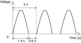
Charge indicator white/green control signal
a30zzw00001992
|
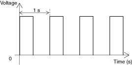
Charge indicator amber control signal
a30zzw00001993
|