 |
a30zzn00002116
EV CONTROL SYSTEM [(E)]
id3040002000e1
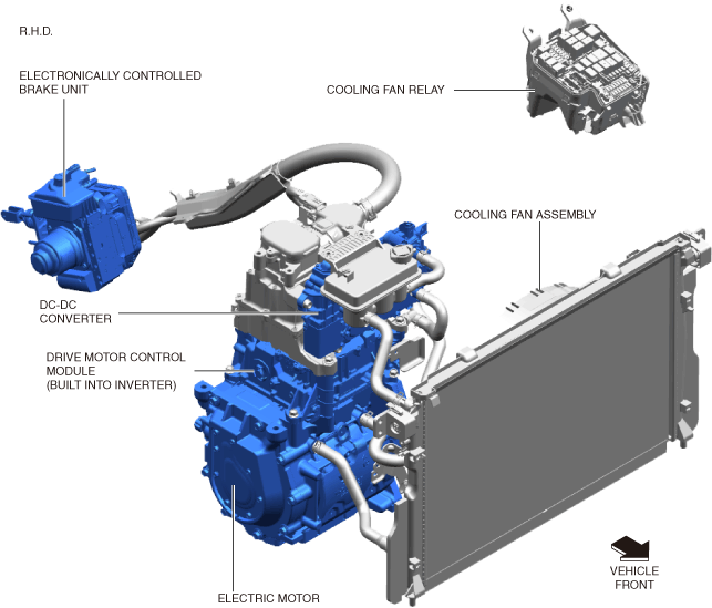
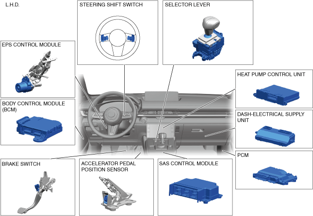
Outline
Structural View
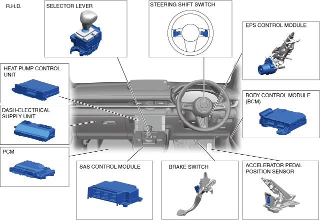
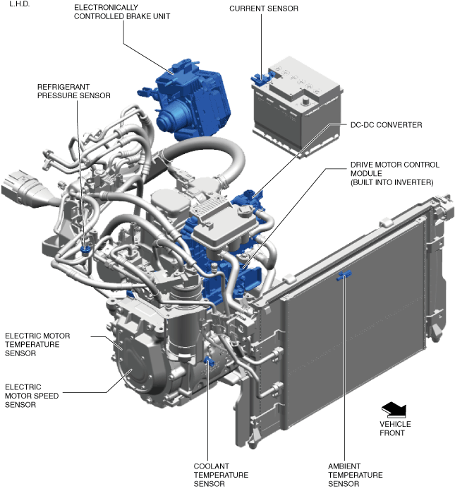
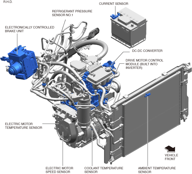
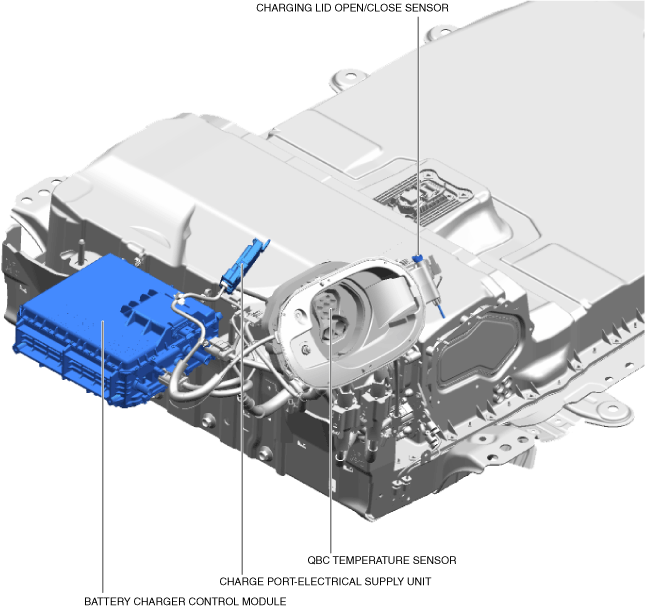
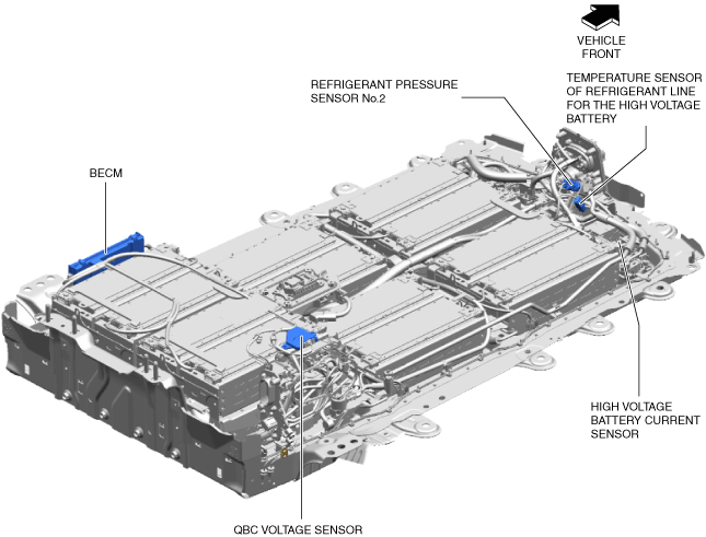
Input parts
a30zzn00002116
|
a30zzn00002123
|
a30zzn00001170
|
a30zzn00002124
|
a30zzn00002117
|
a30zzn00001171
|
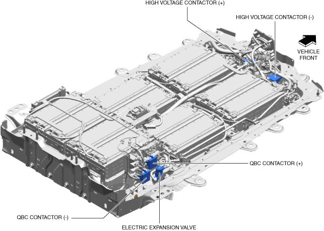
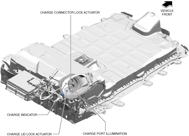
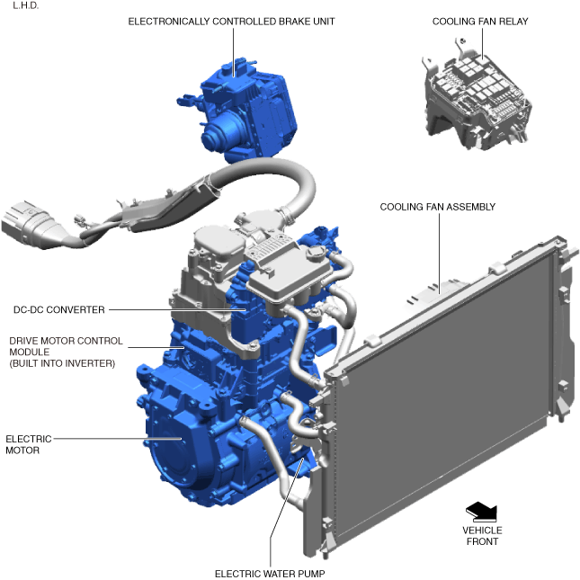
Output parts
a30zzn00000909
|
a30zzn00000910
|
a30zzn00001172
|
a30zzn00002125
|
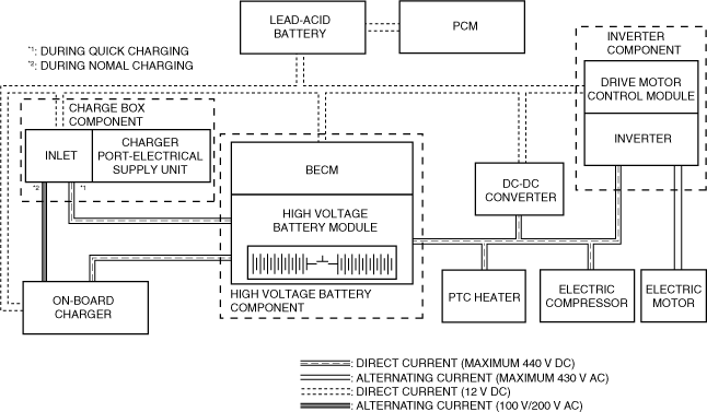
System Diagram
a30zzn00001173
|
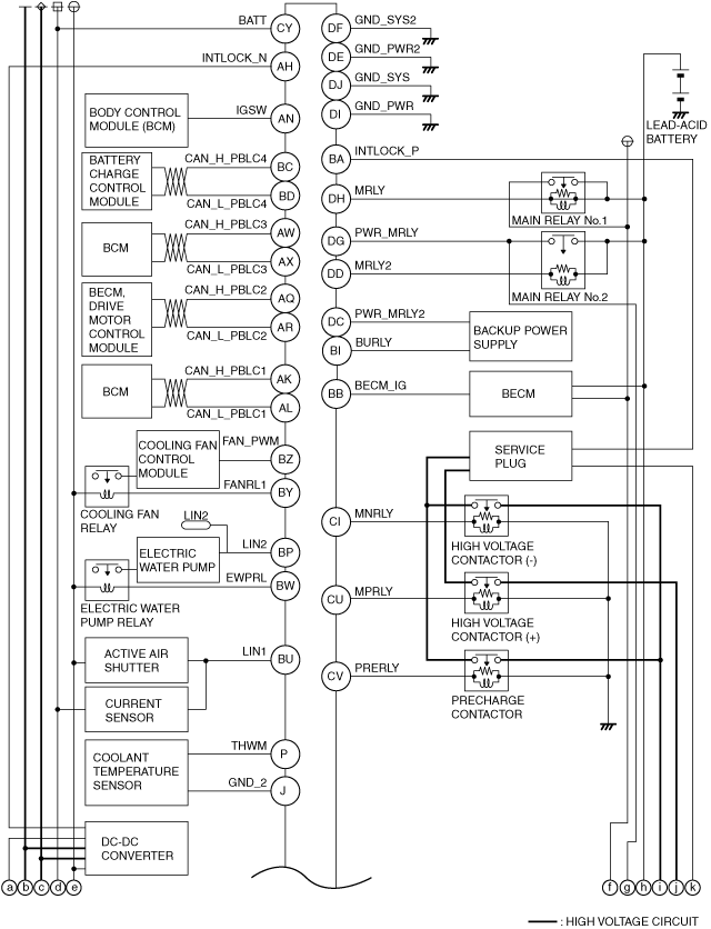
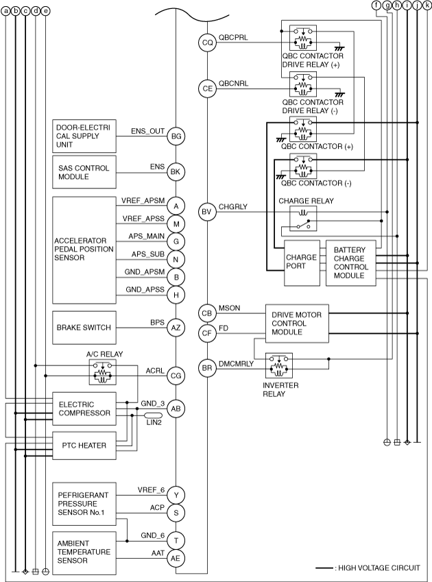
System Wiring Diagram
PCM
a30zzn00001174
|
a30zzn00002118
|
|
Terminal |
Signal |
Input/Output |
Description |
|---|---|---|---|
|
A
|
VREF_APSM
|
—
|
APP sensor No.1 power supply
|
|
B
|
GND_APSM
|
—
|
APP sensor No.1 ground
|
|
C
|
—
|
—
|
—
|
|
D
|
—
|
—
|
—
|
|
E
|
—
|
—
|
—
|
|
F
|
—
|
—
|
—
|
|
G
|
APS_MAIN
|
Input
|
APP sensor No.1 signal
|
|
H
|
GND_APSS
|
—
|
APP sensor No.2 ground
|
|
I
|
—
|
—
|
—
|
|
J
|
GND_2
|
—
|
Coolant temperature sensor ground
|
|
K
|
—
|
—
|
—
|
|
L
|
—
|
—
|
—
|
|
M
|
VREF_APSS
|
—
|
APP sensor No.2 power supply
|
|
N
|
APS_SUB
|
Input
|
APP sensor No.2 signal
|
|
O
|
—
|
—
|
—
|
|
P
|
THWM
|
Input
|
Coolant temperature sensor signal
|
|
Q
|
—
|
—
|
—
|
|
R
|
—
|
—
|
—
|
|
S
|
ACP
|
Input
|
Refrigerant pressure sensor No.1 signal
|
|
T
|
GND_6
|
—
|
Refrigerant pressure sensor No.1, ambient temperature sensor ground
|
|
U
|
—
|
—
|
—
|
|
V
|
—
|
—
|
—
|
|
W
|
—
|
—
|
—
|
|
X
|
—
|
—
|
—
|
|
Y
|
VREF_6
|
—
|
Refrigerant pressure sensor No.1 power supply
|
|
Z
|
—
|
—
|
—
|
|
AA
|
—
|
—
|
—
|
|
AB
|
GND_3
|
—
|
Electric compressor, PTC heater control ground
|
|
AC
|
—
|
—
|
—
|
|
AD
|
—
|
—
|
—
|
|
AE
|
AAT
|
Input
|
Ambient temperature sensor signal
|
|
AF
|
—
|
—
|
—
|
|
AG
|
—
|
—
|
—
|
|
AH
|
INTLOCK_N
|
—
|
Interlock switch ground
|
|
AI
|
—
|
—
|
—
|
|
AJ
|
—
|
—
|
—
|
|
AK
|
CAN_H_PBLC1
|
—
|
CAN communication line (VEHICLE-BUS)
|
|
AL
|
CAN_L_PBLC1
|
—
|
CAN communication line (VEHICLE-BUS)
|
|
AM
|
—
|
—
|
—
|
|
AN
|
IGSW
|
Input
|
IG1 power supply
|
|
AO
|
—
|
—
|
—
|
|
AP
|
—
|
—
|
—
|
|
AQ
|
CAN_H_PBLC2
|
—
|
CAN communication line (AT-BUS)
|
|
AR
|
CAN_L_PBLC2
|
—
|
CAN communication line (AT-BUS)
|
|
AS
|
—
|
—
|
—
|
|
AT
|
—
|
—
|
—
|
|
AU
|
—
|
—
|
—
|
|
AV
|
—
|
—
|
—
|
|
AW
|
CAN_H_PBLC3
|
—
|
CAN communication line (PT-BUS)
|
|
AX
|
CAN_L_PBLC3
|
—
|
CAN communication line (PT-BUS)
|
|
AY
|
—
|
—
|
—
|
|
AZ
|
BPS
|
Input
|
Brake switch signal
|
|
BA
|
INTLOCK_P
|
Input
|
Interlock switch signal
|
|
BB
|
BECM_IG
|
Input
|
PCM start request signal
|
|
BC
|
CAN_H_PBLC4
|
—
|
CAN communication line (PT-Local-BUS)
|
|
BD
|
CAN_L_PBLC4
|
—
|
CAN communication line (PT-Local-BUS)
|
|
BE
|
—
|
—
|
—
|
|
BF
|
—
|
—
|
—
|
|
BG
|
ENS_OUT
|
Input
|
Collision signal (front passenger’s door-electrical supply unit)
|
|
BH
|
—
|
—
|
—
|
|
BI
|
BURLY
|
—
|
Backup power supply
|
|
BJ
|
—
|
—
|
—
|
|
BK
|
ENS
|
Input
|
Collision signal (SAS control module)
|
|
BL
|
—
|
—
|
—
|
|
BM
|
—
|
—
|
—
|
|
BN
|
—
|
—
|
—
|
|
BO
|
—
|
—
|
—
|
|
BP
|
LIN2
|
—
|
LIN communication (electric compressor, PTC heater, electric water pump)
|
|
BQ
|
—
|
—
|
—
|
|
BR
|
DMCMRLY
|
Output
|
Inverter relay control signal
|
|
BS
|
—
|
—
|
—
|
|
BT
|
—
|
—
|
—
|
|
BU
|
LIN1
|
—
|
LIN communication (lead-acid battery current sensor, active air shutter)
|
|
BV
|
CHGRLY
|
Output
|
Charge relay control signal
|
|
BW
|
EWPRL
|
Output
|
Electric water pump relay control signal
|
|
BX
|
—
|
—
|
—
|
|
BY
|
FANRL1
|
Output
|
Cooling fan relay control signal
|
|
BZ
|
FAN_PWM
|
Output
|
Cooling fan control signal
|
|
CA
|
—
|
—
|
—
|
|
CB
|
MSON
|
Output
|
Electric motor servo connection/block signal
|
|
CC
|
—
|
—
|
—
|
|
CD
|
—
|
—
|
—
|
|
CE
|
QBCNRL
|
Output
|
QBC contactor (-) drive relay control signal
|
|
CF
|
FD
|
Output
|
Discharge request signal
|
|
CG
|
ACRL
|
Output
|
A/C relay control signal
|
|
CH
|
—
|
—
|
—
|
|
CI
|
MNRLY
|
Output
|
High voltage contactor (-) control signal
|
|
CJ
|
—
|
—
|
—
|
|
CK
|
—
|
—
|
—
|
|
CL
|
—
|
—
|
—
|
|
CM
|
—
|
—
|
—
|
|
CN
|
—
|
—
|
—
|
|
CO
|
—
|
—
|
—
|
|
CP
|
—
|
—
|
—
|
|
CQ
|
QBCPRL
|
Output
|
QBC contactor (+) drive relay control signal
|
|
CR
|
—
|
—
|
—
|
|
CS
|
—
|
—
|
—
|
|
CT
|
—
|
—
|
—
|
|
CU
|
MPRLY
|
Output
|
High voltage contactor (+) control signal
|
|
CV
|
PRERLY
|
Output
|
Pre-charge contactor control signal
|
|
CW
|
—
|
—
|
—
|
|
CX
|
—
|
—
|
—
|
|
CY
|
BATT
|
—
|
Lead-acid battery power supply
|
|
CZ
|
—
|
—
|
—
|
|
DA
|
—
|
—
|
—
|
|
DB
|
—
|
—
|
—
|
|
DC
|
PWR_MRLY2
|
—
|
Backup power supply
|
|
DD
|
MRLY2
|
Output
|
Main relay No.2 control signal
|
|
DE
|
GND_PWR2
|
—
|
Output ground
|
|
DF
|
GND_SYS2
|
—
|
Signal ground
|
|
DG
|
PWR_MRLY
|
—
|
Main relay No.2 power supply
|
|
DH
|
MRLY
|
Output
|
Main relay No.1 control signal
|
|
DI
|
GND_PWR
|
—
|
Output ground
|
|
DJ
|
GND_SYS
|
—
|
Signal ground
|
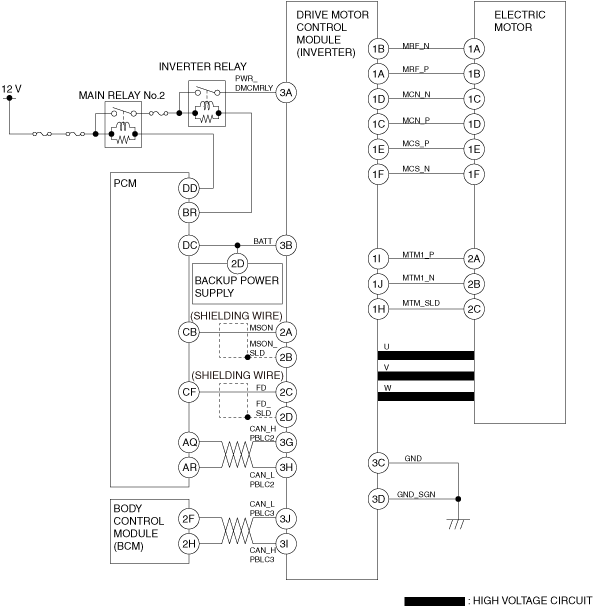
Drive Motor Control Modele
a30zzn00002119
|
|
Terminal |
Signal |
Input/Output |
Description |
|---|---|---|---|
|
1A
|
MRF_P
|
Output
|
Electric motor speed sensor energizing coil output
|
|
1B
|
MRF_N
|
—
|
Electric motor speed sensor energizing coil ground
|
|
1C
|
MCN_P
|
Input
|
Electric motor speed sensor Cos signal
|
|
1D
|
MCN_N
|
—
|
Electric motor speed sensor Cos ground
|
|
1E
|
MCS_P
|
Input
|
Electric motor speed sensor Sin signal
|
|
1F
|
MCS_N
|
—
|
Electric motor speed sensor Sin ground
|
|
1G
|
—
|
—
|
—
|
|
1H
|
MTM_SLD
|
—
|
Shielding wire
|
|
1I
|
MTM1_P
|
Input
|
Electric motor temperature sensor signal
|
|
1J
|
MTM1_N
|
—
|
Electric motor temperature sensor ground
|
|
1K
|
—
|
—
|
—
|
|
1L
|
—
|
—
|
—
|
|
2A
|
MSON
|
Input
|
Electric motor servo connection/block signal
|
|
2B
|
MSON_SLD
|
—
|
Shielding wire
|
|
2C
|
FD
|
Input
|
Discharge request signal
|
|
2D
|
FD_SLD
|
—
|
Shielding wire
|
|
2E
|
—
|
—
|
—
|
|
2F
|
—
|
—
|
—
|
|
2G
|
—
|
—
|
—
|
|
2H
|
—
|
—
|
—
|
|
2I
|
—
|
—
|
—
|
|
2J
|
—
|
—
|
—
|
|
3A
|
PWR_DMCMRLY
|
—
|
Drive motor control module relay power supply
|
|
3B
|
BATT
|
—
|
Backup power supply
|
|
3C
|
GND
|
—
|
Output ground
|
|
3D
|
GND_SGN
|
—
|
Signal ground
|
|
3E
|
—
|
—
|
—
|
|
3F
|
—
|
—
|
—
|
|
3G
|
CAN_H_PBLC2
|
—
|
CAN communication line (AT-BUS)
|
|
3H
|
CAN_L_PBLC2
|
—
|
CAN communication line (AT-BUS)
|
|
3I
|
CAN_H_PBLC3
|
—
|
CAN communication line (PT-BUS)
|
|
3J
|
CAN_L_PBLC3
|
—
|
CAN communication line (PT-BUS)
|
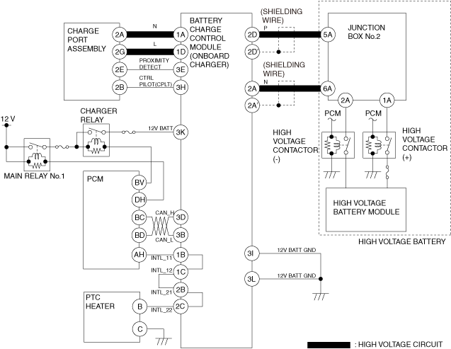
Battery Charge Control Module
a30zzn00002120
|
|
Terminal |
Signal |
Input/Output |
Description |
|---|---|---|---|
|
1A
|
N
|
—
|
Normal charging current input (high AC voltage)
|
|
1B
|
INTL_11
|
—
|
Interlock signal
|
|
1C
|
INTL_12
|
—
|
Interlock signal
|
|
1D
|
L
|
—
|
Normal charging current input (high AC voltage)
|
|
2A
|
N
|
—
|
Normal charging current output (high DC voltage)
|
|
2B
|
INTL_21
|
—
|
Interlock signal
|
|
2C
|
INTL_22
|
—
|
Interlock signal
|
|
2D
|
P
|
—
|
Normal charging current output (high DC voltage)
|
|
3A
|
—
|
—
|
—
|
|
3B
|
CAN L
|
—
|
CAN communication line (PT-Local-BUS)
|
|
3C
|
—
|
—
|
—
|
|
3D
|
CAN H
|
—
|
CAN communication line (PT-Local-BUS)
|
|
3E
|
PROXIMITY DETECT
|
Input
|
Normal charging connector installation status signal
|
|
3F
|
—
|
—
|
—
|
|
3G
|
—
|
—
|
—
|
|
3H
|
CTRL PILOT(CPLT)
|
—
|
CPLT communication
|
|
3I
|
12V BATT GND
|
—
|
Ground
|
|
3J
|
—
|
—
|
—
|
|
3K
|
12V BATT
|
—
|
Lead-acid battery power supply
|
|
3L
|
12V BATT GND
|
—
|
Ground
|
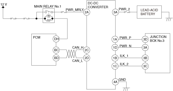
DC-DC Converter
a30zzn00001178
|
|
Terminal |
Signal |
Input/Output |
Description |
|---|---|---|---|
|
1A
|
PWR_P
|
—
|
High voltage power supply (+)
|
|
1B
|
INK_1
|
—
|
Interlock signal
|
|
1C
|
INK_2
|
—
|
Interlock signal
|
|
1D
|
PWR_N
|
—
|
High voltage power supply (-)
|
|
2A
|
PWR_MRLY
|
—
|
Main relay No.1 power supply
|
|
2B
|
—
|
—
|
—
|
|
2C
|
CAN_H
|
—
|
CAN communication line (PT-Local-BUS)
|
|
2D
|
CAN_L
|
—
|
CAN communication line (PT-Local-BUS)
|
|
2E
|
—
|
—
|
—
|
|
2F
|
—
|
—
|
—
|
|
3A
|
PWR_2
|
—
|
Lead-acid battery power supply
|
|
4A
|
GND
|
—
|
Ground
|
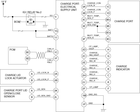
Charge Port - Electrical Supply Unit
a30zzn00002121
|
|
Terminal |
Signal |
Input/Output |
Description |
|---|---|---|---|
|
1A
|
—
|
—
|
—
|
|
1B
|
—
|
—
|
—
|
|
1C
|
CAN_H_PBLC
|
—
|
CAN communication line (PT-Local-BUS)
|
|
1D
|
—
|
—
|
—
|
|
1E
|
—
|
—
|
—
|
|
1F
|
CAN_L_PBLC
|
—
|
CAN communication line (PT-Local-BUS)
|
|
1G
|
BATT
|
—
|
Lead-acid battery power supply
|
|
1H
|
—
|
—
|
—
|
|
1I
|
IG1
|
—
|
IG1 power supply
|
|
1J
|
BATT2
|
—
|
Lead-acid battery power supply
|
|
1K
|
—
|
—
|
—
|
|
1L
|
—
|
—
|
—
|
|
1M
|
GND_SIG
|
—
|
Signal ground
|
|
1N
|
—
|
—
|
—
|
|
1O
|
—
|
—
|
—
|
|
1P
|
GND
|
—
|
Output ground
|
|
1Q
|
—
|
—
|
—
|
|
1R
|
—
|
—
|
—
|
|
1S
|
—
|
—
|
—
|
|
1T
|
—
|
—
|
—
|
|
1U
|
—
|
—
|
—
|
|
1V
|
—
|
—
|
—
|
|
1W
|
—
|
—
|
—
|
|
1X
|
—
|
—
|
—
|
|
2A
|
LID_LOCK_N
|
Output
|
Charging port lid unlock signal
|
|
2B
|
LID_LOCK_P
|
Output
|
Charging port lid lock signal
|
|
2C
|
CHARGE_IND_VSUP
|
—
|
Charging indicator power supply
|
|
2D
|
CHARGE_LAMP_VSUP
|
—
|
Charging port illumination power supply
|
|
2E
|
CHARGE_IND_W
|
Output
|
Charging indicator (white) control signal
|
|
2F
|
CP_LAMP
|
Output
|
Charging port illumination control signal
|
|
2G
|
CHARGE_IND_G
|
Output
|
Charging indicator (green) control signal
|
|
2H
|
CHARGE_IND_U
|
Output
|
Charging indicator (amber) control signal
|
|
2I
|
—
|
—
|
—
|
|
2J
|
CHARGE_IND_R
|
Output
|
Charging indicator (red) control signal
|
|
2K
|
LID_SEN
|
Input
|
Charging port lid open/close sensor signal
|
|
2L
|
LID_SEN_GND
|
—
|
Charging port lid open/close sensor ground
|
|
3A
|
CHARGE_CON_LOCK_N
|
Output
|
Charging connector lock actuator unlock signal
|
|
3B
|
CHARGE_CON_LOCK_P
|
Output
|
Charging connector lock actuator lock signal
|
|
3C
|
INLET_TEMP_SEN_P
|
Input
|
Rapid charging port temperature sensor (+side) signal
|
|
3D
|
—
|
—
|
—
|
|
3E
|
INLET_TEMP_SEN_END
|
—
|
Charging port temperature sensor ground
|
|
3F
|
INLET_TEMP_SEN_N
|
Input
|
Rapid charging port temperature sensor (-side) signal
|
|
3G
|
—
|
—
|
—
|
|
3H
|
—
|
—
|
—
|
Correlation Diagram
Input signal/part
|
Item |
EV system output control |
Electric G-vectoring control plus (e-GVC Plus) |
High voltage circuit start/cut off control |
Auxiliary device power charging system |
DC-DC converter control |
Electronically controlled brake cooperation control |
Battery monitoring system |
High voltage battery charging control |
Charge indicator control |
Charge port illumination control |
Charge connecter lock actuator control |
Battery heater control |
High voltage battery cooling control |
Electric water pump control |
Cooling fan control |
|
|---|---|---|---|---|---|---|---|---|---|---|---|---|---|---|---|---|
|
Drive force control |
Inverter control |
|||||||||||||||
|
Accelerator pedal position sensor
|
×
|
—
|
—
|
—
|
—
|
—
|
—
|
—
|
—
|
—
|
—
|
—
|
—
|
—
|
×
|
—
|
|
Brake switch
|
×
|
—
|
—
|
—
|
—
|
—
|
—
|
—
|
—
|
—
|
—
|
—
|
—
|
—
|
×
|
—
|
|
Coolant temperature sensor
|
×
|
—
|
—
|
—
|
—
|
—
|
—
|
—
|
—
|
—
|
—
|
—
|
—
|
—
|
×
|
×
|
|
Interlock switch
|
—
|
—
|
—
|
×
|
—
|
—
|
—
|
—
|
—
|
—
|
—
|
—
|
—
|
—
|
—
|
—
|
|
Electric motor speed sensor*1
|
—
|
×
|
—
|
—
|
—
|
—
|
—
|
—
|
—
|
—
|
—
|
—
|
—
|
—
|
—
|
—
|
|
Electric motor temperature sensor*1
|
—
|
×
|
—
|
—
|
—
|
—
|
—
|
—
|
—
|
—
|
—
|
—
|
—
|
—
|
—
|
—
|
|
Voltage sensor (in inverter) *1
|
—
|
×
|
—
|
—
|
—
|
—
|
—
|
—
|
—
|
—
|
—
|
—
|
—
|
—
|
—
|
—
|
|
Current sensor (in inverter) *1
|
—
|
×
|
—
|
—
|
—
|
—
|
—
|
—
|
—
|
—
|
—
|
—
|
—
|
—
|
—
|
—
|
|
Power transistor temperature sensor (in inverter) *1
|
—
|
×
|
—
|
—
|
—
|
—
|
—
|
—
|
—
|
—
|
—
|
—
|
—
|
—
|
—
|
—
|
|
ABS wheel speed sensor*4
|
—
|
×
|
—
|
—
|
—
|
—
|
×
|
—
|
—
|
—
|
—
|
—
|
—
|
—
|
—
|
—
|
|
Brake fluid pressure sensor*4
|
—
|
—
|
—
|
—
|
—
|
—
|
×
|
—
|
—
|
—
|
—
|
—
|
—
|
—
|
—
|
—
|
|
Lead-acid battery voltage
|
—
|
—
|
—
|
—
|
—
|
×
|
—
|
—
|
—
|
—
|
—
|
—
|
—
|
—
|
—
|
—
|
|
Refrigerant pressure sensor No.2 (in high voltage battery) *2
|
—
|
—
|
—
|
—
|
—
|
—
|
—
|
×
|
—
|
—
|
—
|
—
|
—
|
×
|
—
|
×
|
|
Temperature sensor of refrigerant line for the high voltage battery (in high voltage battery) *2
|
—
|
—
|
—
|
—
|
—
|
—
|
—
|
×
|
—
|
—
|
—
|
—
|
—
|
×
|
—
|
×
|
|
High voltage battery current sensor (in high voltage battery) *2
|
—
|
—
|
—
|
—
|
—
|
—
|
×
|
×
|
—
|
—
|
—
|
—
|
×
|
—
|
—
|
—
|
|
Cell voltage sensor (in high voltage battery) *2
|
—
|
—
|
—
|
—
|
—
|
—
|
×
|
×
|
—
|
—
|
—
|
—
|
×
|
—
|
—
|
—
|
|
High voltage battery module temperature sensor (in high voltage battery) *2
|
—
|
—
|
—
|
—
|
—
|
—
|
×
|
×
|
—
|
—
|
—
|
—
|
×
|
×
|
—
|
—
|
|
QBC voltage sensor (in high voltage battery) *2
|
—
|
—
|
—
|
—
|
—
|
—
|
—
|
×
|
—
|
—
|
—
|
—
|
—
|
—
|
—
|
—
|
|
Steering shift switch*3
|
—
|
—
|
—
|
—
|
—
|
—
|
×
|
|
—
|
—
|
—
|
—
|
—
|
—
|
—
|
—
|
|
Charging port lid open/closed sensor*5
|
—
|
—
|
—
|
—
|
—
|
—
|
—
|
—
|
—
|
—
|
×
|
—
|
—
|
—
|
—
|
—
|
|
Selector lever
|
×
|
—
|
—
|
—
|
—
|
—
|
—
|
—
|
—
|
×
|
—
|
—
|
—
|
—
|
×
|
—
|
|
Electronically controlled brake unit
|
×
|
—
|
×
|
—
|
—
|
—
|
×
|
—
|
—
|
—
|
—
|
—
|
—
|
—
|
—
|
×
|
|
EPS control module
|
—
|
—
|
×
|
—
|
—
|
—
|
—
|
—
|
—
|
—
|
—
|
—
|
—
|
—
|
—
|
—
|
|
BECM
|
×
|
—
|
—
|
×
|
—
|
—
|
×
|
×
|
×
|
×
|
—
|
×
|
×
|
×
|
—
|
—
|
|
Drive motor control module
|
—
|
—
|
—
|
—
|
—
|
—
|
×
|
—
|
—
|
—
|
—
|
—
|
—
|
—
|
×
|
×
|
|
Dash-electrical supply unit
|
×
|
—
|
—
|
—
|
—
|
—
|
—
|
—
|
—
|
—
|
—
|
—
|
—
|
—
|
—
|
—
|
|
DC-DC converter
|
×
|
—
|
—
|
—
|
—
|
—
|
—
|
—
|
—
|
—
|
—
|
—
|
—
|
—
|
×
|
×
|
|
i-ACTIVSENSE related module
|
×
|
—
|
—
|
—
|
—
|
—
|
—
|
—
|
—
|
—
|
—
|
—
|
—
|
—
|
—
|
—
|
|
Battery charge control module
|
—
|
—
|
—
|
×
|
—
|
—
|
—
|
—
|
×
|
×
|
—
|
×
|
×
|
—
|
×
|
×
|
|
Body control module (BCM)
|
×
|
—
|
—
|
×
|
—
|
—
|
×
|
—
|
×
|
—
|
—
|
—
|
×
|
—
|
—
|
—
|
|
SAS control module
|
—
|
—
|
—
|
×
|
—
|
—
|
—
|
—
|
—
|
—
|
—
|
—
|
—
|
—
|
—
|
×
|
|
Heat pump control unit
|
—
|
—
|
—
|
×
|
—
|
—
|
—
|
—
|
—
|
—
|
—
|
—
|
—
|
×
|
×
|
×
|
|
Charge port-electrical supply unit
|
—
|
—
|
—
|
—
|
—
|
—
|
—
|
—
|
—
|
—
|
×
|
—
|
—
|
—
|
—
|
—
|
|
Each module
|
—
|
—
|
—
|
—
|
×
|
×
|
—
|
—
|
—
|
—
|
—
|
—
|
—
|
—
|
—
|
—
|
Output signal/part
|
Item |
EV system output control |
Electric G-vectoring control plus (e-GVC Plus) |
High voltage circuit start/cut off control |
Auxiliary device power charging system |
DC-DC converter control |
Electronically controlled brake cooperation control |
Battery monitoring system |
High voltage battery charging control |
Charge indicator control |
Charge port illumination control |
Charge connecter lock actuator control |
Battery heater control |
High voltage battery cooling control |
Electric water pump control |
Cooling fan control |
|
|---|---|---|---|---|---|---|---|---|---|---|---|---|---|---|---|---|
|
Drive force control |
Inverter control |
|||||||||||||||
|
High voltage battery contactor/Precharge contactor
|
—
|
—
|
—
|
×
|
×
|
—
|
—
|
—
|
×
|
—
|
—
|
—
|
—
|
—
|
—
|
—
|
|
QBC contactor drive relay
|
—
|
—
|
—
|
×
|
—
|
—
|
—
|
—
|
×
|
—
|
—
|
—
|
—
|
—
|
—
|
—
|
|
Inverter*1
|
—
|
×
|
—
|
—
|
—
|
—
|
×
|
—
|
—
|
—
|
—
|
—
|
—
|
—
|
—
|
—
|
|
Electric water pump
|
—
|
—
|
—
|
—
|
—
|
—
|
—
|
—
|
—
|
—
|
—
|
—
|
—
|
—
|
×
|
—
|
|
Cooling fan control module
|
—
|
—
|
—
|
—
|
—
|
—
|
—
|
—
|
—
|
—
|
—
|
—
|
—
|
—
|
—
|
×
|
|
Cooling fan relay
|
—
|
—
|
—
|
—
|
—
|
—
|
—
|
—
|
—
|
—
|
—
|
—
|
—
|
—
|
—
|
×
|
|
Main relay
|
—
|
—
|
—
|
—
|
—
|
—
|
—
|
—
|
×
|
—
|
—
|
×
|
—
|
—
|
—
|
—
|
|
Battery heater contactor*2
|
—
|
—
|
—
|
—
|
—
|
—
|
—
|
—
|
—
|
—
|
—
|
—
|
×
|
—
|
—
|
—
|
|
Electric expansion valve*2
|
—
|
—
|
—
|
—
|
—
|
—
|
—
|
—
|
—
|
—
|
—
|
—
|
—
|
×
|
—
|
—
|
|
2way valve for refrigerant*3
|
—
|
—
|
—
|
—
|
—
|
—
|
—
|
—
|
—
|
—
|
—
|
—
|
—
|
×
|
—
|
—
|
|
3way valve for refrigerant*3
|
—
|
—
|
—
|
—
|
—
|
—
|
—
|
—
|
—
|
—
|
—
|
—
|
—
|
×
|
—
|
—
|
|
Charge indicator*4
|
—
|
—
|
—
|
—
|
—
|
—
|
—
|
—
|
—
|
×
|
—
|
—
|
—
|
—
|
—
|
—
|
|
Charge port illumination*4
|
—
|
—
|
—
|
—
|
—
|
—
|
—
|
—
|
—
|
—
|
×
|
—
|
—
|
—
|
—
|
—
|
|
Charge connector lock actuator*4
|
—
|
—
|
—
|
—
|
—
|
—
|
—
|
—
|
—
|
—
|
—
|
×
|
—
|
—
|
—
|
—
|
|
Charge lid lock actuator*4
|
—
|
—
|
—
|
—
|
—
|
—
|
—
|
—
|
—
|
—
|
—
|
—
|
—
|
—
|
—
|
—
|
|
Electric compressor
|
—
|
—
|
—
|
—
|
—
|
—
|
—
|
—
|
—
|
—
|
—
|
—
|
—
|
×
|
—
|
—
|
|
Drive motor control module
|
×
|
—
|
×
|
—
|
—
|
—
|
×
|
—
|
—
|
—
|
—
|
—
|
—
|
—
|
—
|
—
|
|
DC-DC converter
|
—
|
—
|
—
|
—
|
×
|
×
|
—
|
—
|
—
|
—
|
—
|
—
|
—
|
—
|
—
|
—
|
|
Electronically controlled brake unit
|
—
|
—
|
×
|
—
|
—
|
—
|
×
|
—
|
—
|
—
|
—
|
—
|
—
|
—
|
—
|
—
|
|
Body control module (BCM)
|
—
|
—
|
—
|
—
|
×
|
—
|
—
|
×
|
×
|
—
|
—
|
—
|
×
|
—
|
—
|
—
|
|
Instrument cluster
|
—
|
—
|
—
|
—
|
—
|
—
|
—
|
×
|
—
|
—
|
—
|
—
|
—
|
—
|
—
|
—
|
|
Charge port-electrical supply unit
|
—
|
—
|
—
|
—
|
—
|
—
|
—
|
—
|
×
|
×
|
—
|
—
|
—
|
—
|
—
|
—
|
|
BECM
|
—
|
—
|
—
|
—
|
—
|
—
|
×
|
—
|
—
|
—
|
—
|
—
|
×
|
—
|
—
|
—
|
|
Heat pump control unit
|
—
|
—
|
—
|
—
|
—
|
—
|
—
|
—
|
—
|
—
|
—
|
—
|
—
|
×
|
—
|
—
|