DRIVE FORCE CONTROL
id304000200200
Outline
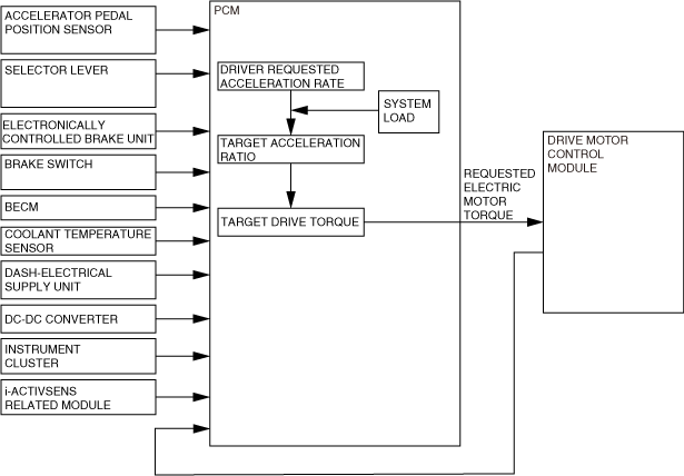
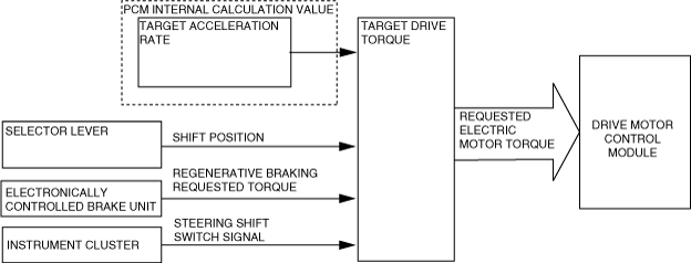
• The PCM calculates the output requested by the driver and the output according to the vehicle conditions and sends an electric motor drive torque request signal to the drive motor control module.
Block Diagram
Operation
Calculation of requested electric motor torque
-
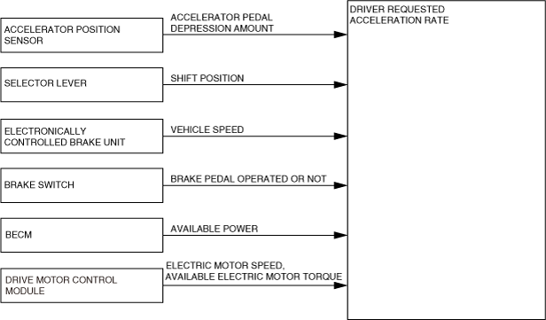
1. Driver requested acceleration rate
-
• The PCM detects the driver’s driving operations from the accelerator pedal position signal, the brake switch signal, and the shift position signal. Additionally, it detects the vehicle status from the vehicle speed and the high voltage battery and electric motor status input via CAN communication.
• If the PCM detects that the brake pedal is depressed with the accelerator pedal depressed, it changes the driver requested acceleration speed to 0. As a result, the vehicle can be stopped safety by increasing the priority of the brake operation compared to the acceleration pedal operation. (Brake override function)
• The PCM calculates the acceleration rate requested by the driver based on this detected information.
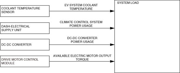
2. System load
• The PCM detects the heat generation condition from the load on the EV system by the signal from the coolant temperature sensor. Additionally, it detects the system load condition from the climate control system power usage, DC-DC converter power usage, and available electric motor output torque input via CAN communication.
• The PCM calculates the system load condition based on this detected information.
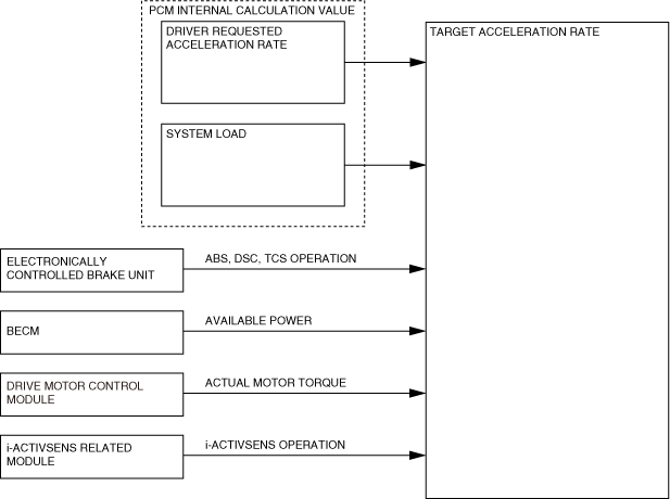
3. Target acceleration rate
• The PCM displays the i-ACTIVSENSE operation status, such as the ABS, DSC, TCS, the Mazda radar cruise control (MRCC) via CAN communication, and it calculates the operation status of the vehicle controls from the available power of the high voltage battery and the actual torque generated by the electric motor.
• The PCM calculates the target acceleration rate based on the driver requested acceleration rate calculated at 1. and 2., the system load, and the detected information.
4. Target drive torque
• The PCM detects the vehicle’s direction of travel and the amount of regenerative braking based on the shift position received from the selector lever and the regenerative braking requested torque input from the electronically controlled brake unit via CAN communication. Additionally, it detects a signal indicating the target acceleration rate by the operation of the steering wheel paddles based on the steering shift switch signal received from the instrument cluster via CAN communication. (See
Deceleration and acceleration rate change using steering wheel paddles.)
• The PCM calculates the target driving force based on the target acceleration rate, rotation direction, and regenerative braking condition calculated in 3. Additionally, the calculated target driving force is sent to the drive motor control module as the requested electric motor torque.
Deceleration and acceleration rate change using steering wheel paddles
-
Outline
-
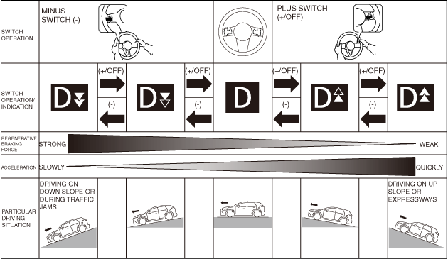
• Steering wheel paddles improve the speed control performance of the accelerator pedal. When the minus switch (-) on the left side of the steering wheel is operated, the regenerative braking deceleration rate is increased and the acceleration rate is decreased. In addition, when the plus switch (+/OFF) on the right side of the steering wheel is operated, the regenerative braking deceleration rate is decreased and the acceleration rate is increased. As a result, the driver can intuitively control the deceleration rate by the electric motor regenerative braking when the accelerator pedal is released, and control the vehicle speed with predictability in a wide range of driving situations such as driving on up or down slopes, while in heavy traffic, or driving at high speeds.
-
Operation
-
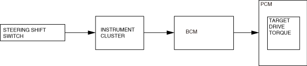
• The PCM uses the target acceleration rate due to the operation of the steering wheel paddles based on the steering shift switch operation signal received via CAN communication through the instrument cluster and body control module (BCM).
• When the minus switch (-) on the steering shift switch is operated from the D position, the regenerative braking deceleration rate is increased in 2 steps in the order of [D▾▽] and [D▽ ▽ ], and the acceleration rate is decreased. Whereas, when the plus switch (+/OFF) on the steering shift switch is operated from the D position, the regenerative braking deceleration rate is decreased in 2 steps in the order of [D▴ △] and [D △ △ ], and the acceleration rate is increased.
• When the plus switch (+/OFF) on the steering shift switch continues to be pulled for a certain period of time or more, the set value returns to the initial setting (D). In addition, the selected setting is canceled under the following conditions.
-
― Selector lever is shifted to any position from D
― Main power is switched OFF using power switch
• A steering wheel paddle operation signal is canceled while the Mazda radar cruise control (MRCC) system is operating.
• The relationship between the regenerative braking deceleration rate and the acceleration rate using the steering wheel paddles is as shown in the following figure.