INVERTER CONTROL
id304000200400
Outline
• The PCM drives the power transistors in the inverter through the drive motor control module to achieve the required electric motor torque calculated from the vehicle conditions. As a result, the electric motor is driven and power is generated according to the vehicle conditions.
• The PCM not only controls the high voltage battery contactors to cut off the high voltage circuit when the EV system is stopped by the normal power switch operation or when the airbag deployment signal is received from the SAS control module, but it also assures the safety of the high voltage circuit by driving power transistors of all phases and consuming (discharging) the power using the electric motor.
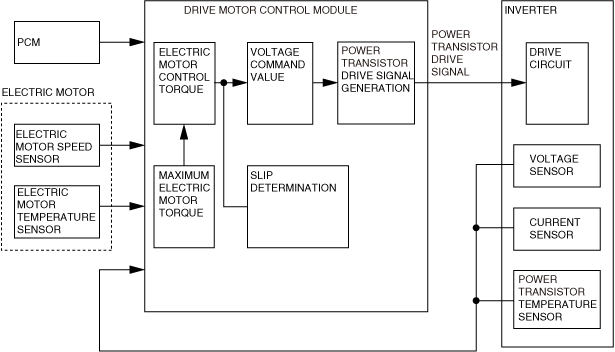
Block Diagram
Operation
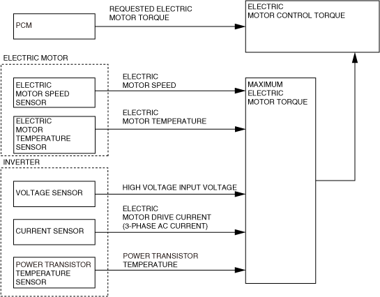
1. Electric motor control torque
• The drive motor control module inputs the electric motor temperature, rotation speed, the high voltage input voltage from the inverter, the 3-phase AC current which drives the electric motor, and the power transistor temperature signal, and it detects the electric motor drive system conditions.
• The drive motor control module calculates the maximum electric motor torque which can assure the reliability of system parts based on these input signals.
• The drive motor control module calculates the electric motor control torque so as to not exceed the requested electric motor torque from the PCM and the calculated maximum electric motor torque.
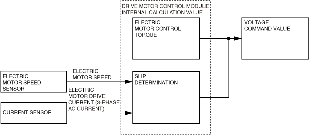
2. Voltage command value
• If the driving wheels free-spin (slip), excess voltage and excess current occurs which may damage the inverter internally. For this reason, the drive motor control module determines if slipping is occurring based on the electric motor rotation speed and the 3-phase AC current signal which drives the electric motor. Additionally, if the drive motor control module determines that slipping is occurring, it requests a torque reduction.
• The drive motor control module calculates the voltage command based on the electric motor control torque calculated in 1., and the calculated slip determination and torque reduction request amount so that no electric motor slip occurs.
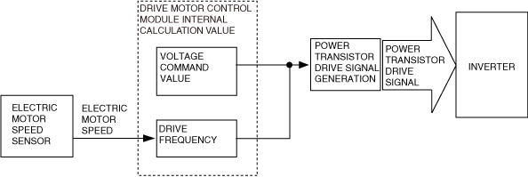
3. Power transistor drive signal
• The drive motor control module calculates the electric motor drive frequency based on the electric motor rotation speed.
• The drive motor control module generates the power transistor drive signal based on the voltage command value calculated in 2., and the calculated drive frequency. Additionally, it sends the generated power transistor drive signal to the inverter.