INTERLOCK SWITCH


id304000202200


Purpose, Function

•  The interlock switches detect the exposure of a high voltage terminal as basic information for connecting and cutting off the high voltage circuit.
•  The PCM detects whether the high voltage terminal is exposed or not based on the signal which changes according to the interlock switch circuit status.

Construction

•  The interlock switches are installed to the following locations.
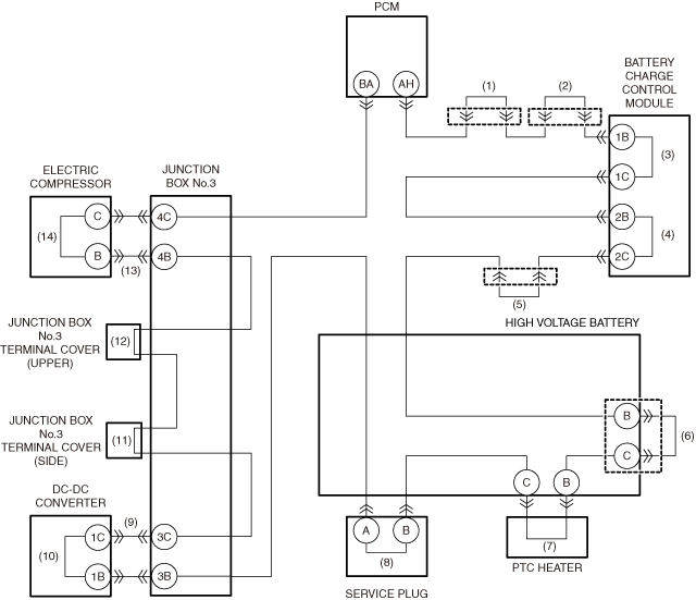
―  Intermediate connectors (+ side (1), minus side (2)) of high voltage wiring harness between quick charge port and high voltage battery
―  Onboard charger high voltage connectors (2 locations) (3) / (4)
―  Intermediate connector of high voltage wiring harness between onboard charger and high voltage battery (5)
―  High voltage battery-side connector of power cable between high voltage battery and junction box No.3 (6)
―  PTC heater high voltage connector (7)
―  Service plug (8)
―  DC-DC converter high voltage connectors (junction box No.3 side (9), DC-DC converter side (10))
―  Junction box No.3 terminal cover (side) (11)
―  Junction box No.3 terminal cover (upper) (12)
―  Electric compressor high voltage connectors (junction box No.3 side (13), electric compressor side (14))
•  The interlock switches are installed in a series on the circuit.
a30zzn00002513

Operation

•  If any high voltage related part with an interlock switch is removed or a high voltage wiring harness is disconnected, the detection circuit will be disconnected. As a result, the PCM detects that the high voltage circuit is exposed.
•  When the PCM detects an open circuit in the detection circuit, it controls the operation of the high voltage contactors and inhibits and cuts off connections to the high voltage circuit. (See HIGH VOLTAGE CIRCUIT START/CUT OFF CONTROL.)