SERVICE CAUTIONS
id000000700900
Injury/damage Prevention Precautions
• Depending on the vehicle, the cooling fan may operate suddenly even when the ignition is switched off. Therefore, keep hands and tools away from the cooling fan even if the cooling fan is not operating to prevent injury to personnel or damage to the cooling fan. Always disconnect the negative battery terminal when servicing the cooling fan or parts near the cooling fan.
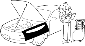
Vehicle Protection
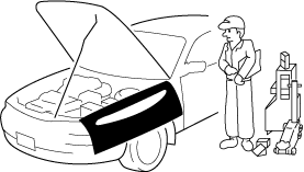
• Before servicing, install the fender cover, seat cover, steering cover, and floor covering.
Tool and Measuring Equipment Preparation
• Before servicing, prepare all necessary tools, measuring equipment, and SSTs listed in the servicing procedure.
Special Service Tools
• If there is an SST instruction in the work procedure, use the applicable SST.
Malfunction diagnosis system
• Use the Mazda modular diagnostic system (M-MDS) for malfunction diagnosis.
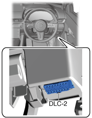
Connection to malfunction diagnosis system
-
• With the ignition switched off, connect the malfunction diagnosis system to the DLC-2 connector shown in the figure.
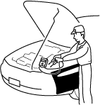
Oil Leakage Inspection
• Use either of the following procedures to identify the type of oil that is leaking:
Using UV light (black light)
1. Remove any oil on the engine or transmission/transaxle.
-
Note
-
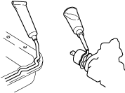
• Referring to the fluorescent dye instruction manual, mix the specified amount of dye into the engine oil or transmission/transaxle oil.
2. Pour the fluorescent dye into the engine oil or transmission/transaxle oil.
3. Allow the engine to run for 30 min.
4. Inspect for dye leakage by irradiating with UV light (black light), and identify the type of oil that is leaking.
5. If no dye leakage is found, allow the engine to run for another 30 min. or drive the vehicle then reinspect.
6. Find where the oil is leaking from, then make necessary repairs.
-
Note
-
• To determine whether it is necessary to replace the oil after adding the fluorescent dye, refer to the fluorescent dye instruction manual.
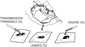
Not using UV light (black light)
1. Gather sample of the leaking oil using an absorbent white tissue.
2. Then, gather some samples of engine and transmission/transaxle oil onto a white cloth or piece of paper.
-
• MT vehicles: transmission/transaxle oil
• AT vehicles: ATF
• CVT vehicles: continuously variable transaxle fluid
3. Compare the appearance and smell, and identify the type of oil that is leaking.
4. Remove any oil on the engine or transmission/transaxle.
5. Allow the engine to run for 30 min.
6. Check the area where the oil is leaking, then make necessary repairs.
Negative Battery Terminal Disconnection/Connection
-
Warning
-
-
Note
-
• Be careful not to close the liftgate with the negative battery terminal disconnected. If the negative battery terminal is disconnected, the liftgate cannot be opened because power is not supplied to the liftgate opener system.
Also, if the battery is discharged, the liftgate cannot be opened because power is not supplied to the liftgate opener system.
• If the liftgate has been closed, perform manual release of the liftgate latch to open the liftgate.
• When disconnecting the negative battery terminal, wrap the liftgate lock striker with a clean rag to prevent the liftgate from closing.
Required procedure after negative battery terminal disconnection/connection
|
System name
|
Conditions after disconnecting the negative battery terminal
|
Required procedure
|
Reference
|
|
Before disconnecting negative battery terminal
|
After connecting negative battery terminal
|
|
i-stop system
|
Specified information in the PCM cleared and the i-stop does not operate normally.
|
—
|
Perform battery condition initial setting (i-stop setting). *
|
|
|
Sunroof system
|
Initial settings are reset, and operations are disabled.
|
—
|
Perform the initial settings of the sunroof system.
|
|
* :For vehicles with i-stop, if the negative battery terminal is disconnected and re-connected, battery condition initial setting (i-stop setting) must be performed.
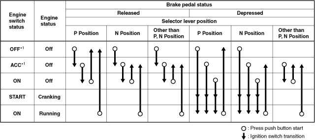
Switch the Power Supply Using the Push Button Start and Start the Engine
• By pressing the push button start under the conditions shown in the figure, the ignition can be switched.
*1 :To switch the ignition to ACC or off from ON (engine on), the vehicle speed must be 5 km/h {3 mph} or less.
Removal of Parts
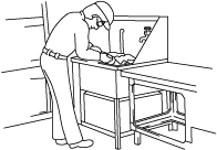
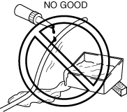
• After determining the damage or malfunction, perform the malfunction diagnosis and perform safe and efficient servicing. Before removing the part, verify the assembled condition, and inspect for deformities and damage. After removing the part, cover it with a clean cloth and packing tape so that foreign matter or small parts do not penetrate it. Place the removed part on a clean workbench, otherwise it may become damaged or lost if it is placed on the floor.
Control module configuration
-
Caution
-
• If the configuration procedure is not completed correctly after replacing a control module which requires configuration, the system will not operate normally. Therefore, perform the configuration in accordance with the replacement procedure in the workshop manual.
• If a control module is replaced, depending on the control module, it may be necessary to write the vehicle specification data to the new control module using the M-MDS. This writing procedure is called configuration.
Disassembly
• When disassembling a complex part, place a marking or alignment mark where performance or external appearance will not be affected so that reassembly can be performed easily and efficiently.
Inspection During Removal and Disassembly
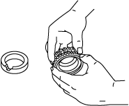
• Visually inspect the assembled condition for deformation and damage each time a part is removed.
Arrangement of Parts
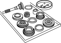
• Arrange the removed/disassembled parts in an orderly fashion so as not to mix them up and not let them become dirty. In addition, separate the parts to be replaced from the parts to be reused.
Cleaning of Parts
• Thoroughly clean and wash the parts to be reused.
Assembly
1. Follow the procedures correctly and observe the standard values (tightening torque, adjustment value) when assembling.
2. When the following parts are removed, replace them with new ones.
|
Oil seal
|
Cotter pin
|
|
Gasket
|
Locknut
|
|
O-ring
|
Roll pin
|
|
Lock washer
|
—
|
3. Depending on the gasket location, apply sealant before installing the part. Install the part before the sealant hardens.
4. Apply oil to the moving components of each part before assembling the part.
5. Apply the specified oil or grease to the specified locations (oil seals) before assembling the part.
Adjustment
• Adjust to the standard using measuring equipment.
Rubber Parts and Tubing
• Prevent gasoline or oil from getting on rubber parts or tubing.
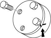
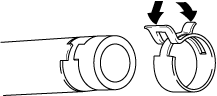
Installing/Removing the Hose Clamp
1. When reusing each hose, install the hose clamp onto the original hose clamp imprint.
2. After installation, apply force to the hose clamp in the direction of the arrows to engage the hose clamp securely.
-
Note
-
• Follow the description in each section because the clamps which are used with the fuel system differ from the above.
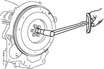
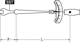
Torque Formulas
• When using a torque wrench together with an SST, use the following formulas to calculate the specified torque value due to the extra length that the SST adds to the torque wrench.
Formula
-
A: The length of the SST exceeding the effective length of the torque wrench.
L: Torque wrench length
N·m ×[L/(L+A)]
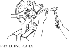
Vise
• When using a vise, insert protective plates into the opening of the vise to prevent damage to the parts.
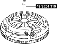
SST
• Some Ford manufactured SSTs are used on the SSTs necessary for servicing.
Be advised that these SSTs are marked with Ford SST numbers.
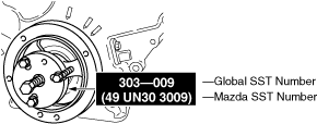
Be advised that the SST numbers of Mazda and Ford are written jointly so that the Ford SST number collates with Mazda as shown in the following description examples in this manual.
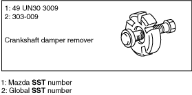
Example of description (special service tool list)
Example of description (in context)