OIL CONTROL VALVE (OCV) INSPECTION [SKYACTIV-G 2.0]
id0110h2801400
-
Warning
-
• A hot engine can cause severe burns. Turn off the engine and wait until it is cool before servicing.
Hydraulic Variable Valve Timing Control System Operation Inspection
When idling cannot be continued
1. Remove the OCV. (See OIL CONTROL VALVE (OCV) REMOVAL/INSTALLATION [SKYACTIV-G 2.0].)
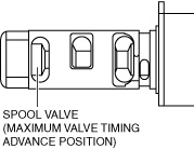
2. Verify that the spool valve is at maximum advanced position.
-
3. Connect the OCV connector.
4. Switch the ignition ON (engine off).
5. Verify that the spool valve is at the maximum advanced position.
-
• If the spool valve is stuck in the retard direction, inspect for the following:
-
― Short circuit in wiring harnesses or connectors between OCV and PCM
-
• If there is no malfunction, go to the next step.
6. Inspect the hydraulic variable valve timing actuator. (See ELECTRIC VARIABLE VALVE TIMING ACTUATOR, HYDRAULIC VARIABLE VALVE TIMING ACTUATOR REMOVAL/INSTALLATION [SKYACTIV-G 2.0].)
When idling can be continued
-
Using The M-MDS
-
1. Connect the M-MDS to the DLC-2.
2. Warm up the engine.
3. Using the PCM simulation function [VLV_TIMING_DSD_EX], verify that the engine speed fluctuates when the OCV duty value is 100%. (See
SIMULATION INSPECTION.)
If the engine speed fluctuates, verify the condition of the timing chain assembly (valve timing).
If the engine speed does not fluctuate, perform the following inspections.
-
2. Inspect the following wiring harnesses and connectors between the OCV and PCM for an open and short circuit.
-
• Between OCV terminal A and PCM terminal 1CO
• Between OCV terminal B and F12 15A fuse, and F12 15A fuse and main relay terminal C
3. Inspect the oil passage for clogging and leakage.
Oil passage
-
― Between engine oil solenoid valve and OCV
― Between OCV and camshaft
― Oil passage inside camshaft
-
Without Using the M-MDS
-
1. Disconnect the OCV connector.
2. Start the engine and idle it.
-
Note
-
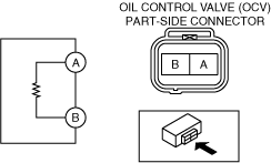
• When applying battery voltage between the OCV terminals, the positive and negative cables can be connected to either terminal A or B.
3. Verify that the engine idles roughly or stalls when battery voltage is applied between OCV terminals A and B.
If the engine idles roughly or stalls, verify the condition of the timing chain assembly (valve timing).
If the engine does not idle roughly or stall, perform the following inspections.
-
2. Inspect the following wiring harnesses and connectors between the OCV and PCM for an open and short circuit.
-
• Between OCV terminal A and PCM terminal 1CO
• Between OCV terminal B and F12 15A fuse, and F12 15A fuse and main relay terminal C
3. Inspect the oil passage for clogging and leakage.
Oil passage
-
― Between engine oil solenoid valve and OCV
― Between OCV and camshaft
― Oil passage inside camshaft
Coil Resistance Inspection
1. Disconnect the negative battery terminal. (See NEGATIVE BATTERY TERMINAL DISCONNECTION/CONNECTION.)
2. Remove the plug hole plate. (See PLUG HOLE PLATE REMOVAL/INSTALLATION [SKYACTIV-G 2.0].)
3. Disconnect the OCV connector.
4. Measure the resistance between terminals A and B using an ohmmeter.
-
OCV coil resistance
-
6.9—7.5 ohms [20°C {68°F}]
-
5. Install in the reverse order of removal.
Spool Valve Operation Inspection
1. Disconnect the negative battery terminal. (See NEGATIVE BATTERY TERMINAL DISCONNECTION/CONNECTION.)
2. Remove the OCV. (See OIL CONTROL VALVE (OCV) REMOVAL/INSTALLATION [SKYACTIV-G 2.0].)
3. Verify that the spool valve in the OCV is in the maximum valve timing advance position as indicated in the figure.
-
4. Verify that the battery is fully charged. (See BATTERY INSPECTION.)
-
-
Note
-
• When applying battery positive voltage between the OCV terminals, the connection can be either of the following:
-
― Positive battery cable to terminal A, negative battery cable to terminal B
― Positive battery cable to terminal B, negative battery cable to terminal A
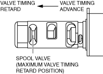
5. Apply battery positive voltage between the OCV terminals and verify that the spool valve operates and moves to the maximum valve timing retard position.
-
6. Stop applying battery positive voltage and verify that the spool valve returns to the maximum valve timing advance position.
-
• If there is no malfunction, go to the next step.
7. Install the OCV. (See OIL CONTROL VALVE (OCV) REMOVAL/INSTALLATION [SKYACTIV-G 2.0].)