am3zzw00034823
|
-
• Standard
-
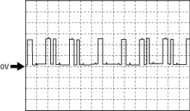
4.8 V or more (Maximum value of wave pattern)0.8 V or less (Minimum value of wave pattern)
-
CAMSHAFT POSITION (CMP) SENSOR INSPECTION [SKYACTIV-G 2.0]
id0140f4801400
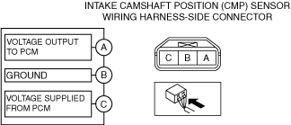
Intake CMP Sensor
Visual inspection
1. Disconnect the negative battery terminal. (See NEGATIVE BATTERY TERMINAL DISCONNECTION/CONNECTION.)
2. Remove the intake CMP sensor. (See CAMSHAFT POSITION (CMP) SENSOR REMOVAL/INSTALLATION [SKYACTIV-G 2.0].)
3. Verify that there are no metal shavings on the intake CMP sensor.
Voltage inspection
1. Idle the engine.
2. Measure the output voltage wave pattern between intake CMP sensor terminals A and B using an oscilloscope.
am3zzw00034823
|
Wave pattern (reference)
adejjw00007911
|
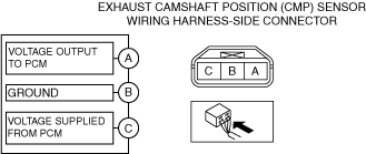
Exhaust CMP Sensor
Visual inspection
1. Disconnect the negative battery terminal. (See NEGATIVE BATTERY TERMINAL DISCONNECTION/CONNECTION.)
2. Remove the exhaust CMP sensor. (See CAMSHAFT POSITION (CMP) SENSOR REMOVAL/INSTALLATION [SKYACTIV-G 2.0].)
3. Verify that there are no metal shavings on the exhaust CMP sensor.
Voltage inspection
1. Idle the engine.
2. Measure the output voltage wave pattern between exhaust CMP sensor terminals A and B using an oscilloscope.
am3zzw00034824
|
Wave pattern (reference)
adejjw00007911
|