REAR DIFFERENTIAL REMOVAL/INSTALLATION
id031400700500
Oil and Chemical Type
|
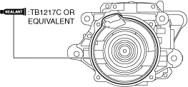
Sealant
Type: TB1217C or equivalent
|
-
Warning
-
• If the vehicle is driven without ending maintenance mode, it could result in an accident. After performing the maintenance mode work, always end maintenance mode.
-
Caution
-
• When performing the procedure while the vehicle is on the ground, block the front and rear wheels using wheel blocks. Otherwise, the vehicle may move when the electric parking brake is released.
• Performing the following procedures could cause an open circuit in the rear ABS wheel-speed sensor wiring harness if it is pulled by mistake. Before servicing, disconnect the rear ABS wheel-speed sensor and set it aside so that the wiring harness will not be pulled by mistake.
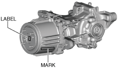
• If the characteristic value of a new coupling component is not input to the PCM or the characteristic value is input incorrectly after replacing the coupling component, it could result in the following conditions.
-
― The system does not operate normally.
― A problem with durability of the coupling component occurs.
-
• Read out the characteristic value of the coupling component from the label or mark shown in the figure.
1. Switch to the maintenance mode. (See MAINTENANCE MODE.)
2. Disconnect the negative battery terminal. (See NEGATIVE BATTERY TERMINAL DISCONNECTION/CONNECTION.)
3. Drain the rear differential oil into a container. (See DIFFERENTIAL OIL REPLACEMENT.)
4. Remove the three-way catalytic converter. (See EXHAUST SYSTEM REMOVAL/INSTALLATION [SKYACTIV-G 2.0])
5. Remove the propeller shaft. (See PROPELLER SHAFT REMOVAL/INSTALLATION.)
6. Remove the rear drive shaft. (See REAR DRIVE SHAFT REMOVAL/INSTALLATION.)
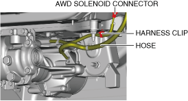
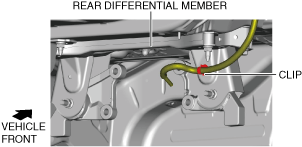
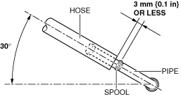
7. Disconnect the hose. (See Hose Installation Note.)
8. Disconnect the AWD solenoid connector and harness clip.
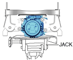
9. Support the rear differential component using a jack.
-
Warning
-
• Always verify that the rear differential component is securely supported by a jack. If the rear differential component falls off, it can cause serious injury or death, and damage to the vehicle.
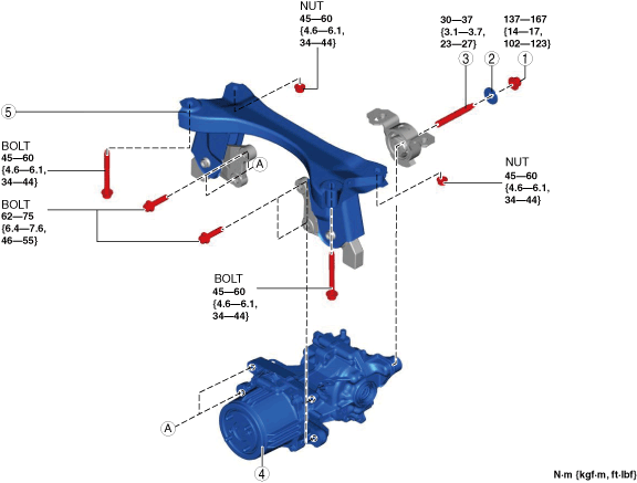
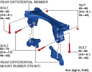
10. Remove in the order indicated in the table.
11. Install in the reverse order of removal.
12. Add the specified rear differential oil. (See DIFFERENTIAL OIL REPLACEMENT.)
13. End the maintenance mode. (See MAINTENANCE MODE.)
|
1
|
Nut
|
|
2
|
Washer
|
|
3
|
Stud bolt
|
|
4
|
Rear differential component
|
|
5
|
Rear differential member
|
|
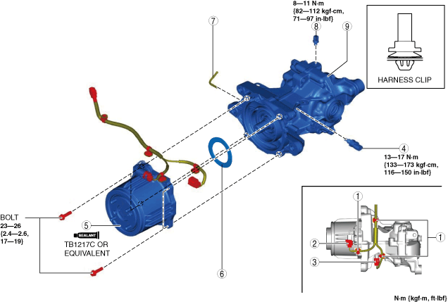
1
|
Harness clip
|
|
2
|
AWD solenoid connector
|
|
3
|
Differential oil temperature sensor connector
|
|
4
|
Differential oil temperature sensor
|
|
5
|
Coupling component
|
|
6
|
Washer
|
|
7
|
Pipe
|
|
8
|
Breather
|
|
9
|
Rear differential
|
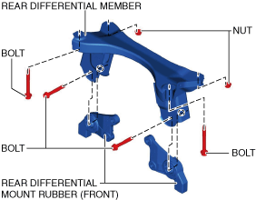
Rear Differential Member Removal Note
1. Detach the clip.
2. Remove the rear differential mount rubber (front).
3. Remove the rear differential member.
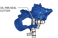
Coupling Component Removal Note
1. Disconnect the coupling component using an oil pan seal cutter.
Coupling Component Installation Note
-
Note
-
• Clean away the remaining silicone sealant before applying new silicone sealant.
• Install the coupling component before the applied silicone sealant starts to harden.
• Add rear differential oil after the silicone sealant hardens.
1. Apply a thin layer of silicone sealant TB1217C or equivalent to the contact surfaces of the coupling component and the rear differential.
2. Install the coupling component to the differential.
3. After replacing the coupling component, read out the characteristic value of a new coupling component and write it to the PCM. (See COUPLING COMPONENT CALIBRATION DATA WRITING.)
Rear Differential Member Installation Note
1. Install the rear differential member.
2. Install the rear differential mount rubber (front).
3. Assemble the clip.
Hose Installation Note
1. Install the hose to the pipe as shown in the figure.
 ac30zw00003084