 |
a30zzn00002070
POWER DOOR AND FUEL-FILLER LID LOCK SYSTEM
id091400705400
Outline
Function
Door lock switch interlock function
Collision detection unlock function
Auto door lock function
Function for locking all doors by lock knob operation without using remote transmitter
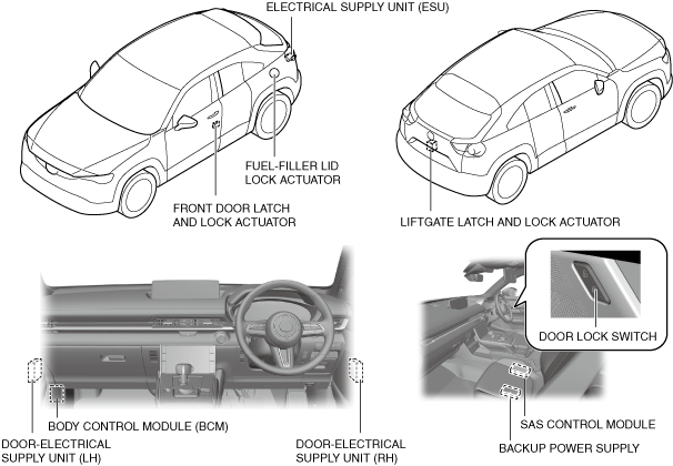
Structural view
a30zzn00002070
|
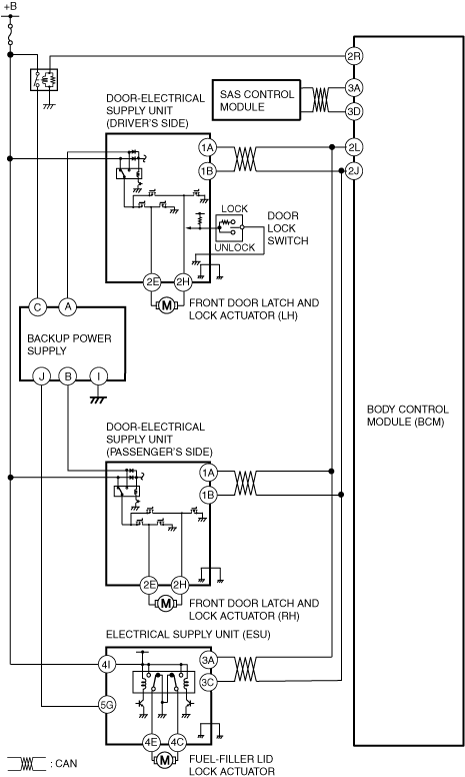
System wiring diagram
a30zzn00002071
|
Operation
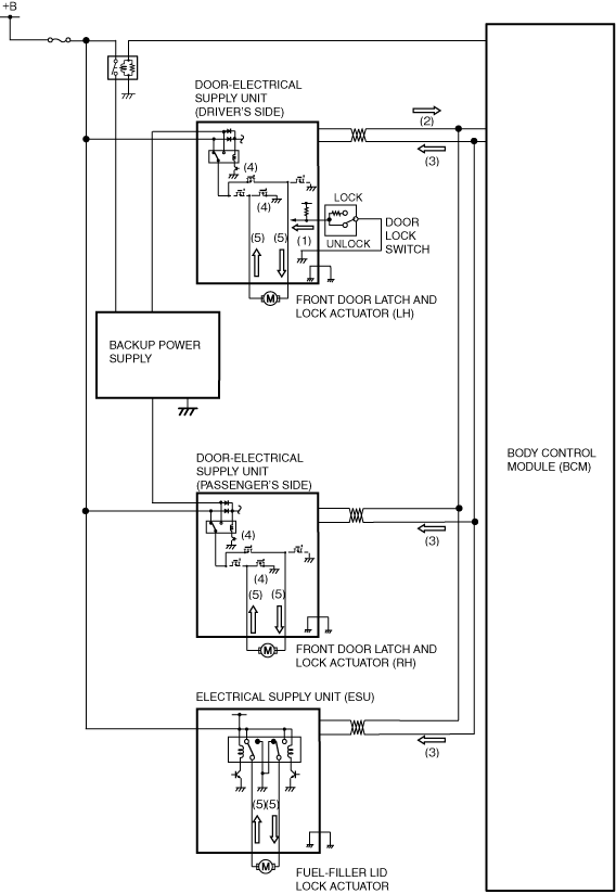
Lock operation using door lock switch
1. When the door-electrical supply unit (driver’s side) detects a door lock switch lock signal (1), it sends a door lock switch lock signal (2) using CAN communication to the body control module (BCM).
2. When the body control module (BCM) receives a door lock switch lock signal (2), it determines the door lock operation and sends an all door lock signal (3) using CAN communication to the door-electrical supply unit (driver’s side) and the door-electrical supply unit (passenger’s side) and electrical supply unit (ESU).
3. When the door-electrical supply unit (driver’s side) and the door-electrical supply unit (passenger’s side) and electrical supply unit (ESU) receive an all door lock signal (3), the door-electrical supply unit (driver’s side) and the door-electrical supply unit (passenger’s side) turns the FET (lock side) on (4), and the electrical supply unit (ESU) turns the transistor on (4) and then the relay turns on (4).
4. When the FET (lock side) turns on (4), the front and rear door latch and lock actuator motors perform a lock operation (5), and the front and rear doors lock. When the relay turns on, the fuel-filler lid lock actuator motor performs a lock operation, and the fuel-filler lid locks.
a30zzn00002072
|
Unlock operation using the door lock switch
1. When the door-electrical supply unit (driver’s side) detects a door lock switch unlock signal (1), it sends a door lock switch unlock signal (2) using CAN communication to the body control module (BCM).
2. When the body control module (BCM) receives a door lock switch unlock signal (2), it determines the door unlock operation and sends an all door unlock signal (3) using CAN communication to the door-electrical supply unit (driver’s side) and the door-electrical supply unit (passenger’s side) and the electrical supply unit (ESU).
3. When the door-electrical supply unit (driver’s side) and the door-electrical supply unit (passenger’s side) and the electrical supply unit (ESU) receive an all door unlock signal (3), the door-electrical supply unit (driver’s side) and the door-electrical supply unit (passenger’s side) turn the transistor on (4) and turn the door unlock relay on (4), at the same time FET (unlock side) on (4), and the electrical supply unit (ESU) turns the transistor on and then the relay turns on.
4. When the door unlock relay (4) and FET (unlock side) turns on (4), the front and rear door latch and lock actuator motors perform an unlock operation (5), and the front and rear doors unlock. When the relay turns on, the fuel-filler lid lock actuator motor performs an unlock operation, and the fuel-filler lid unlock.
a30zzn00002073
|
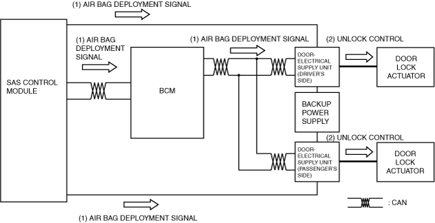
Collision detection unlock function operation
1. When the air bags deploy, the SAS control module sends an air bag deployment signal to the door-electrical supply unit (driver’s side) and the door-electrical supply unit (passenger's side) via CAN signals and electric signals.
2. The door-electrical supply unit (driver’s side) and the door-electrical supply unit (passenger's side) receive the air bag deployment signal and after approx. 6 s, they operate the front door lock actuator motors, and the front doors unlock.
a30zzn00002074
|
Auto Door Lock Operation