 |
a30zzw00006487
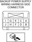
BACKUP POWER SUPPLY INSPECTION
id092100701700
1. Disconnect the negative battery terminal.(See NEGATIVE BATTERY TERMINAL DISCONNECTION/CONNECTION)
2. Remove the backup power supply. (See BACKUP POWER SUPPLY REMOVAL/INSTALLATION.)
3. Connect the backup power supply connector.
4. Connect the negative battery terminal. (See NEGATIVE BATTERY TERMINAL DISCONNECTION/CONNECTION)
5. Verify that the voltages of each of the terminals are as indicated in the terminal voltage table (reference).
Terminal Voltage Table (Reference)
a30zzw00006487
|
|
Terminal |
Signal |
Connected to |
Measurement condition |
Voltage (V) |
Inspection item |
|
|---|---|---|---|---|---|---|
|
A
|
Power supply
|
Door-electrical supply unit (driver’s side)
|
Ignition switched ON (engine off or on)
|
VB
|
• Door-electrical supply unit (driver’s side)
• Related wiring harness
|
|
|
B
|
Power supply
|
Door-electrical supply unit (passenger's side)
|
Ignition switched ON (engine off or on)
|
VB
|
• Door-electrical supply unit (passenger's side)
• Related wiring harness
|
|
|
C
|
Power supply (IG1)
|
F48 7.5A fuse
|
Ignition switched ON (engine off or on)
|
VB
|
• F48 7.5A fuse
• Related wiring harness
|
|
|
Ignition switched OFF (LOCK)
|
1.0 or less
|
|||||
|
D
|
—
|
—
|
—
|
—
|
—
|
|
|
E
|
—
|
—
|
—
|
—
|
—
|
|
|
F
|
—
|
—
|
—
|
—
|
—
|
|
|
G
|
—
|
—
|
—
|
—
|
—
|
|
|
H
|
—
|
—
|
—
|
—
|
—
|
|
|
I
|
GND
|
Body ground
|
Continuous
|
1.0 or less
|
• GND point
• Related wiring harness
|
|
|
J
|
Power supply
|
Electrical Supply Unit
|
Ignition switched ON (engine off or on)
|
VB
|
• Electrical Supply Unit
• Related wiring harness
|
|