 |
am6zzw00008262
RELAY AND FUSE BLOCK INSTALLATION
id092100702100
Replacement Part
|
Band
Quantity: 2
Location of use: Relay and fuse block lower cover
|
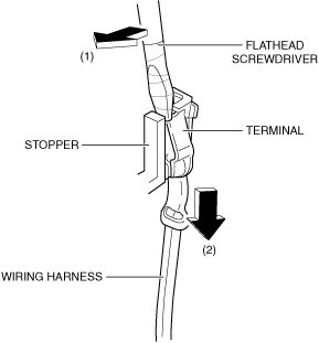
1. Move the flathead screwdriver in the direction of the arrow (1) shown in the figure, and pull the wiring harness in the direction of the arrow (2) while pressing the stopper to detach the relay or fuse terminal from the stopper.
am6zzw00008262
|
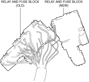
2. Relocate all relay and fuse terminals to the new relay and fuse block.
am6zzw00008263
|
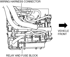
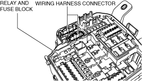
3. Connect the connectors.
a30zzw00006422
|
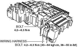
4. Install the wiring harness.
a30zzw00006423
|
5. Install the bolt.
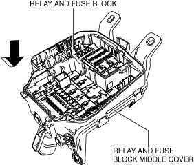
6. Insert the relay and fuse block middle cover into the relay and fuse block.
a30zzw00006424
|
7. Insert the wiring harness connectors into the relay and fuse block middle cover.
a30zzw00006425
|
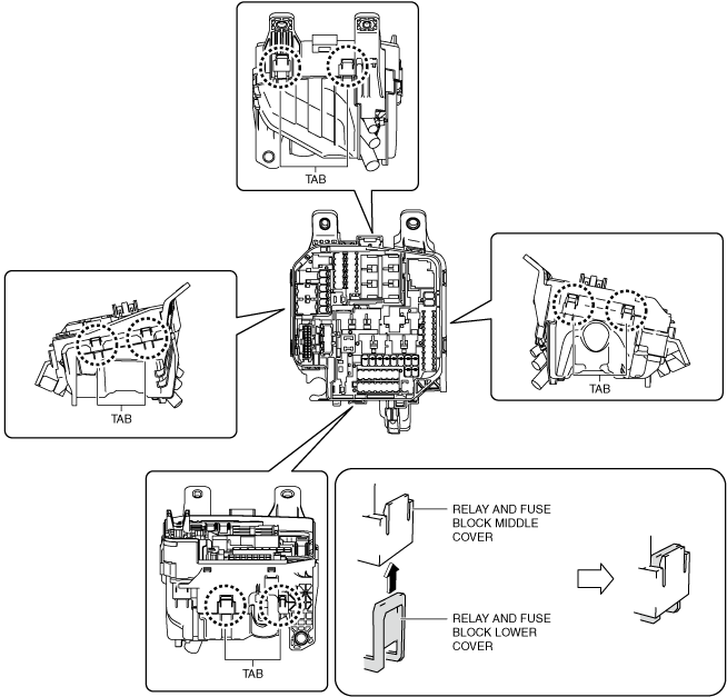
8. Insert all the relay and fuse block middle cover tabs into the relay and fuse block lower cover and install the relay and fuse block lower cover.
a30zzw00006426
|
9. Install the relay and fuse block lower to the relay and fuse block middle cover.
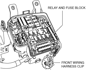
10. Install the wiring harness clip to the relay and fuse block lower cover.
a30zzw00006427
|
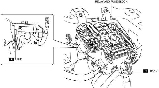
11. Install the band shown in the figure.
a30zzw00006428
|
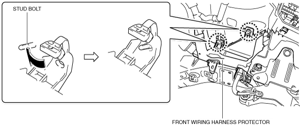
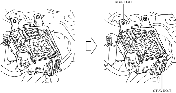
12. Insert the front wiring harness protector into the stud bolts.
a30zzw00006429
|
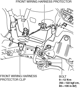
13. Install the front wiring harness protector clip tabs to the body.
a30zzw00006430
|
14. Install the body ground and then install the bolts.
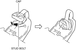
15. Insert the front wiring harness protector cap into the stud bolt.
a30zzw00006431
|
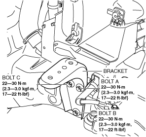
16. Install the bracket.
a30zzw00006441
|
17. Install nut A.
18. Install nut B.
19. Install nut C.
20. Insert the relay and fuse block into the stud bolts.
a30zzw00006442
|
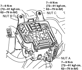
21. Install nut A.
a30zzw00006443
|
22. Install nut B.
23. Install nut C.
24. Install all the relays and fuses.
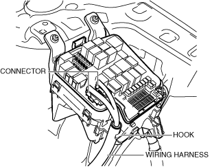
25. Connect the connectors.
a30zzw00006444
|
26. Press the wiring harness to the relay and fuse block hook.
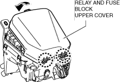
27. Install the relay and fuse block upper cover.
a30zzw00006445
|
28. Install the following parts.
29. Perform the "Verify Relay and Fuse Block Replacement". (See Verify relay and fuse block replacement.)
30. Connect the negative battery terminal. (See NEGATIVE BATTERY TERMINAL DISCONNECTION/CONNECTION.)
Verify relay and fuse block replacement
1. Temporarily connect the negative battery terminal to verify that the related wiring harness is not heated.
2. Switch the ignition ON (engine off).
3. Verify that the fuse is not blown and the related wiring harness is not heated.
4. Inspect for DTCs. (See DTC INSPECTION.)
5. If there is no malfunction in Step 1, 3, and 4, start the engine and maintain the idle status.
6. Operate all the switches of the interior/exterior lights of the vehicle and verify that all the lights illuminate/flash.
7. Operate the audio, climate control, wiper switch, and selector lever (ATX) and verify that they operate correctly.
8. Shift the selector lever to the P position, race the engine at approx. 3,000 rpm from engine idling, and verify that there is no malfunction. (ATX)
9. Perform a road test and verify that low speed, acceleration, shift-up, and shift-down conditions are normal. (ATX)