 |
a30zzw00001760
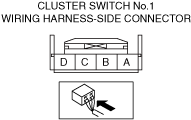
PARKING SENSOR OFF SWITCH INSPECTION
id092200705000
1. Disconnect the negative battery terminal. (See NEGATIVE BATTERY TERMINAL DISCONNECTION/CONNECTION.)
2. Disconnect the cluster switch No.1 connector. (See CLUSTER SWITCH REMOVAL/INSTALLATION.)
3. Connect the negative battery terminal. (See NEGATIVE BATTERY TERMINAL DISCONNECTION/CONNECTION.)
4. Attach the tester lead to the cluster switch No.1 wiring harness-side connector and inspect voltage or continuity according to the Terminal Voltage Table (Reference) on the table.
Terminal Voltage Table (Reference)
a30zzw00001760
|
|
Terminal |
Connected to |
Test item |
Test condition |
Specification |
Inspection item(s) |
|---|---|---|---|---|---|
|
A
|
Instrument cluster
|
Continuity
|
Cluster switch No.1 terminal A—Instrument cluster B
|
Continuity
|
• Instrument cluster
• Related wiring harness
|
|
B
|
• IG1 relay No.2
• F47 15A fuse
|
Voltage
|
Ignition is switched ON (engine off)
|
B+
|
• IG1 relay No.2
• F47 15A fuse
• Related wiring harness
|
|
Except above
|
1.0 V or less
|
||||
|
C
|
Instrument cluster
|
Continuity
|
Cluster switch No.1 terminal C—Instrument cluster AI
|
Continuity
|
• Instrument cluster
• Related wiring harness
|
|
D
|
Ground point
|
Voltage
|
Under any condition
|
Approx. 0
|
• GND point
• Related wiring harness
|