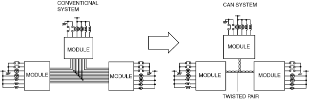
ac5uun00002862
|
MULTIPLEX COMMUNICATION SYSTEM
id100000001400
Outline
ac5uun00002862
|
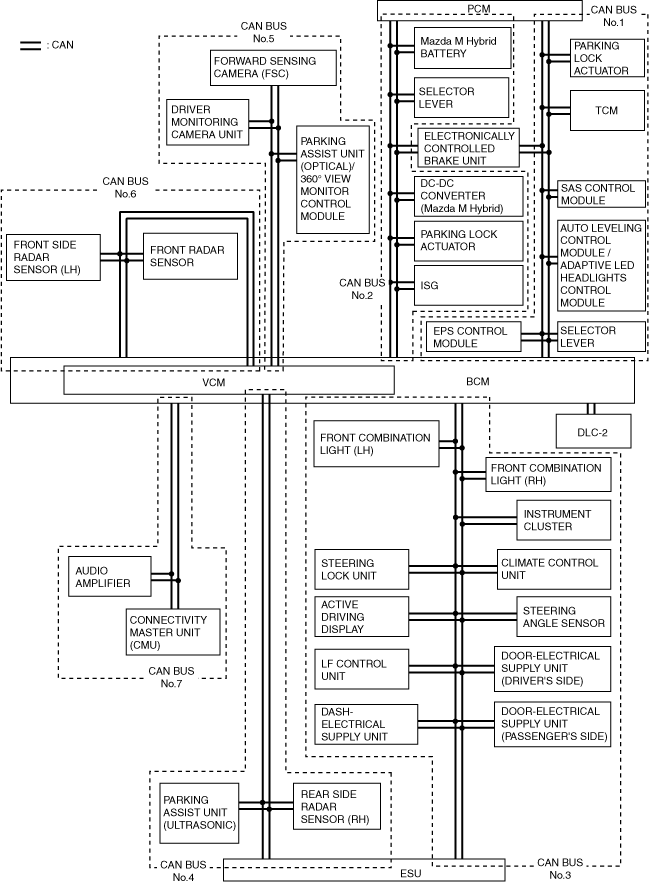
System Wiring Diagram
CAN communication
a30zzn00001531
|
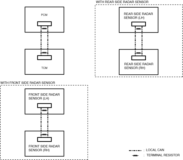
Local CAN
a30zzn00001532
|
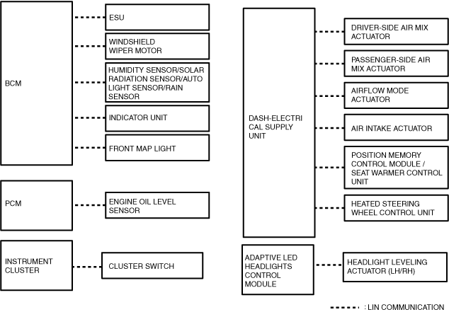
LIN communication
a30zzn00001533
|
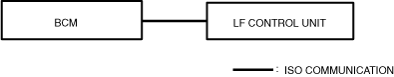
ISO communication
a30zzn00001081
|
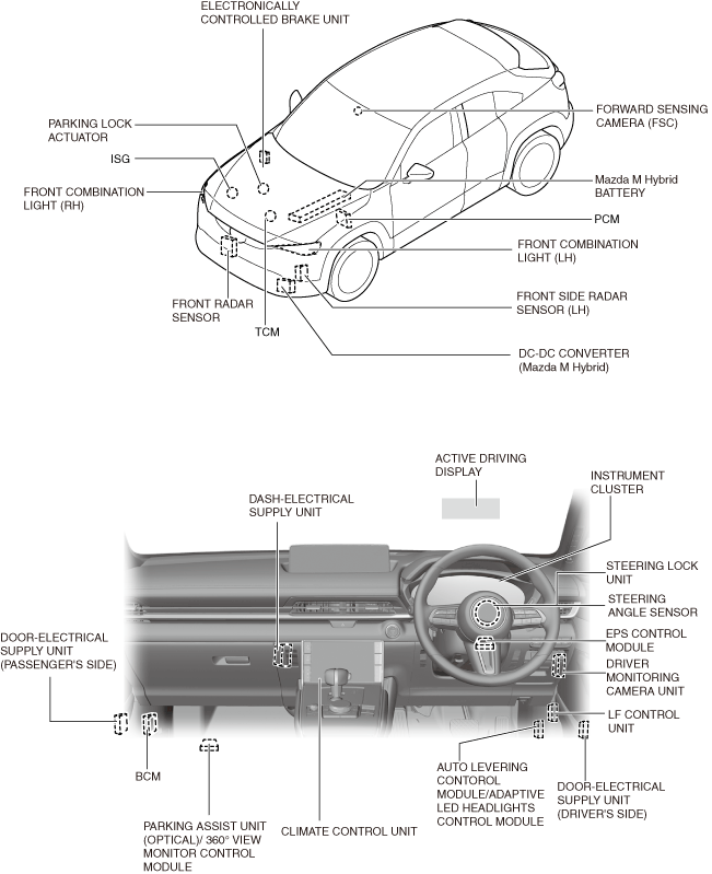
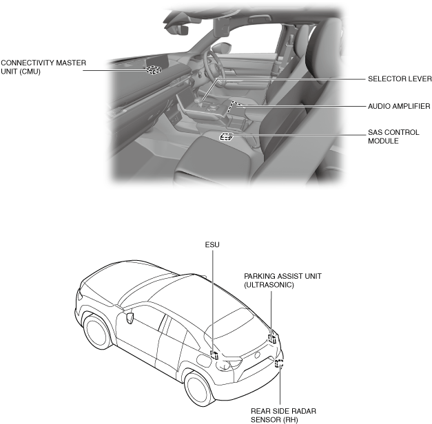
Structural View
a30zzn00001534
|
a30zzn00001520
|
Function
CAN (controller area network) system
Local CAN
LIN communication
ISO communication
Construction
CAN
Local CAN
LIN communication
ISO communication