 |
a30zzw00005411
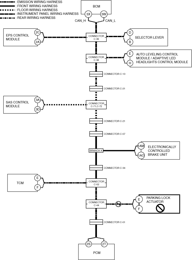
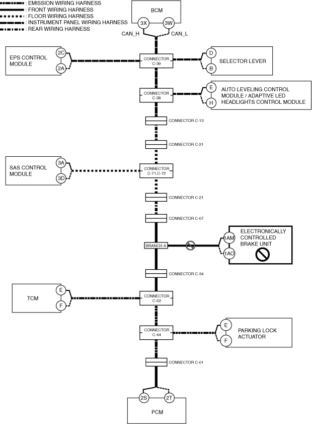
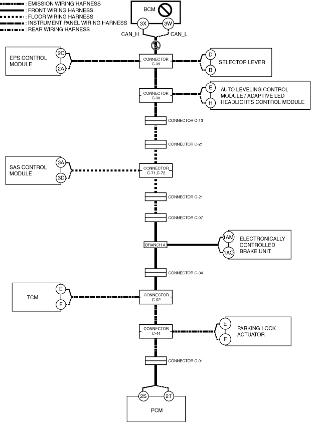
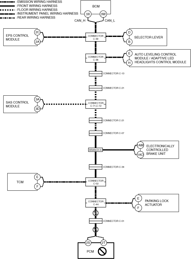
DETERMINING OPEN CIRCUIT LOCATION (CAN-BUS No.1)
id100200001700
1. Verify the CAN system-related module DTCs and the module displayed in red or blue on the M-MDS screen.
2. Apply the communication error DTC and the module displayed in red or blue to the DTC output pattern and malfunctioning location, and select the possible cause for the diagnostic result and the reference for the inspection item. (See DTC Output Pattern And Malfunctioning Location.)
3. Inspect the possible cause and inspection item of the applicable malfunctioning part.
DTC Output Pattern And Malfunctioning Location
|
M-MDS display |
DTC |
DTC output pattern and malfunctioning location |
|||||||||||||
|---|---|---|---|---|---|---|---|---|---|---|---|---|---|---|---|
|
DTC output module |
|||||||||||||||
|
PCM
|
U0100:00
|
||||||||||||||
|
U0103:00
|
×
|
||||||||||||||
|
U0121:00
|
×
|
||||||||||||||
|
U0129:00
|
×
|
||||||||||||||
|
U0131:00
|
×
|
||||||||||||||
|
U0140:00
|
×
|
||||||||||||||
|
U0151:00
|
×
|
||||||||||||||
|
U0155:00
|
|||||||||||||||
|
U0164:00
|
|||||||||||||||
|
U01BA:00
|
×
|
||||||||||||||
|
U0291:00
|
×
|
||||||||||||||
|
U102D:00
|
×
|
||||||||||||||
|
U2121:00
|
|||||||||||||||
|
U212E:00
|
|||||||||||||||
|
U2131:00
|
|||||||||||||||
|
U2133:00
|
|||||||||||||||
|
EPS control module
|
U0100:00
|
×
|
×
|
×
|
×
|
×
|
×
|
||||||||
|
U0121:00
|
×
|
×
|
×
|
×
|
|||||||||||
|
U0140:00
|
×
|
||||||||||||||
|
U2121:00
|
|||||||||||||||
|
Electronically controlled brake unit
|
U0100:00
|
×
|
×
|
×
|
|||||||||||
|
U0101:00
|
×
|
×
|
|||||||||||||
|
U0131:00
|
×
|
||||||||||||||
|
U0140:00
|
×
|
||||||||||||||
|
U0151:00
|
×
|
||||||||||||||
|
U0155:00
|
|||||||||||||||
|
U0164:00
|
|||||||||||||||
|
U2121:00
|
|||||||||||||||
|
U212E:00
|
|||||||||||||||
|
U2131:00
|
|||||||||||||||
|
Vehicle control module (VCM)
|
U0100:00
|
×
|
×
|
×
|
×
|
×
|
×
|
×
|
|||||||
|
U0101:00
|
×
|
×
|
×
|
×
|
×
|
×
|
|||||||||
|
U0121:00
|
×
|
×
|
×
|
×
|
×
|
||||||||||
|
U0126:00
|
|||||||||||||||
|
U0131:00
|
×
|
×
|
|||||||||||||
|
U0140:00
|
×
|
||||||||||||||
|
U0151:00
|
×
|
×
|
×
|
×
|
|||||||||||
|
U0155:00
|
|||||||||||||||
|
U0156:00
|
|||||||||||||||
|
U0164:00
|
|||||||||||||||
|
U2120:00
|
|||||||||||||||
|
U2122:00
|
|||||||||||||||
|
U2123:00
|
|||||||||||||||
|
U2125:00
|
|||||||||||||||
|
U2126:00
|
|||||||||||||||
|
U212E:00
|
|||||||||||||||
|
U2131:00
|
|||||||||||||||
|
U2132:00
|
|||||||||||||||
|
U2133:00
|
|||||||||||||||
|
U2139:00
|
|||||||||||||||
|
U213A:00
|
|||||||||||||||
|
Body control module (BCM)
|
U0100:00
|
×
|
×
|
×
|
×
|
×
|
×
|
×
|
|||||||
|
U0101:00
|
×
|
×
|
×
|
×
|
×
|
×
|
|||||||||
|
U0103:00
|
×
|
||||||||||||||
|
U0103:87
|
×
|
||||||||||||||
|
U0111:00
|
|||||||||||||||
|
U0115:00
|
×
|
×
|
×
|
×
|
×
|
×
|
×
|
||||||||
|
U0120:00
|
|||||||||||||||
|
U0121:00
|
×
|
×
|
×
|
×
|
×
|
||||||||||
|
U0121:87
|
×
|
×
|
×
|
×
|
×
|
||||||||||
|
U0126:00
|
|||||||||||||||
|
U0131:00
|
×
|
×
|
|||||||||||||
|
U0151:00
|
×
|
×
|
×
|
×
|
|||||||||||
|
U0155:00
|
|||||||||||||||
|
U0156:00
|
|||||||||||||||
|
U0158:00
|
|||||||||||||||
|
U0164:00
|
|||||||||||||||
|
U0182:00
|
×
|
×
|
×
|
||||||||||||
|
U01BA:00
|
×
|
||||||||||||||
|
U0316:82
|
|||||||||||||||
|
U2121:49
|
|||||||||||||||
|
U212A:00
|
|||||||||||||||
|
U212D:00
|
|||||||||||||||
|
U212E:00
|
|||||||||||||||
|
U2130:00
|
|||||||||||||||
|
U2131:00
|
|||||||||||||||
|
U2133:00
|
|||||||||||||||
|
U213A:00
|
|||||||||||||||
|
U213B:00
|
|||||||||||||||
|
U213C:00
|
×
|
×
|
×
|
×
|
×
|
||||||||||
|
Connectivity master unit (CMU)
|
U0101:00
|
×
|
×
|
×
|
×
|
×
|
×
|
||||||||
|
U0131:00
|
×
|
×
|
|||||||||||||
|
U0140:00
|
×
|
||||||||||||||
|
U0151:00
|
×
|
×
|
×
|
×
|
|||||||||||
|
U0155:00
|
|||||||||||||||
|
U2121:00
|
|||||||||||||||
|
U213C:00
|
×
|
×
|
×
|
×
|
×
|
||||||||||
|
U213E:00
|
×
|
×
|
×
|
×
|
×
|
×
|
×
|
||||||||
|
Auto leveling control module
|
U0122:87
|
×
|
×
|
×
|
|||||||||||
|
U212A:87
|
|||||||||||||||
|
U212B:87
|
×
|
||||||||||||||
|
U212D:87
|
|||||||||||||||
|
Adaptive LED headlights control module
|
U0122:87
|
×
|
×
|
×
|
|||||||||||
|
U0126:87
|
|||||||||||||||
|
U0155:87
|
|||||||||||||||
|
U2121:87
|
|||||||||||||||
|
U212A:87
|
|||||||||||||||
|
U212B:87
|
×
|
||||||||||||||
|
U212D:87
|
|||||||||||||||
|
Dash-electrical supply unit
|
U0100:00
|
×
|
×
|
×
|
×
|
×
|
×
|
×
|
|||||||
|
U0121:00
|
×
|
||||||||||||||
|
U0151:00
|
×
|
×
|
×
|
×
|
|||||||||||
|
U212B:00
|
×
|
||||||||||||||
|
U212E:00
|
|||||||||||||||
|
U2131:00
|
|||||||||||||||
|
U2133:00
|
|||||||||||||||
|
U213A:00
|
|||||||||||||||
|
SAS control module
|
U0140:00
|
×
|
|||||||||||||
|
U0155:00
|
|||||||||||||||
|
U0156:00
|
|||||||||||||||
|
TCM [ET6A-EL, ET6AX-EL]
|
U0100:00
|
×
|
×
|
||||||||||||
|
U0121:00
|
×
|
||||||||||||||
|
U0131:00
|
×
|
||||||||||||||
|
U0140:00
|
×
|
||||||||||||||
|
U0155:00
|
|||||||||||||||
|
U212C:00
|
|||||||||||||||
|
Integrated starter generator (ISG)
|
U0100:00
|
×
|
×
|
×
|
×
|
×
|
×
|
×
|
|||||||
|
Mazda M Hybrid battery
|
U0100:00
|
×
|
×
|
×
|
×
|
×
|
×
|
×
|
|||||||
|
DC-DC Converter (Mazda M Hybrid)
|
U0100:00
|
×
|
×
|
×
|
×
|
×
|
×
|
×
|
|||||||
|
U212B:00
|
×
|
||||||||||||||
|
Selector lever
|
U0100:00
|
×
|
×
|
×
|
×
|
×
|
×
|
||||||||
|
U0101:00
|
×
|
×
|
×
|
×
|
×
|
||||||||||
|
U0121:00
|
×
|
×
|
×
|
×
|
|||||||||||
|
U0140:00
|
×
|
||||||||||||||
|
U212B:00
|
×
|
||||||||||||||
|
Parking lock actuator
|
U0100:00
|
×
|
|||||||||||||
|
U0115:00
|
×
|
||||||||||||||
|
U0100:41
|
×
|
||||||||||||||
|
U0100:82
|
×
|
||||||||||||||
|
M-MDS display module
|
Module displayed in red or blue
|
||||||||||||||
|
PCM
|
×
|
×
|
×
|
×
|
×
|
×
|
×
|
||||||||
|
Parking lock actuator
|
|
×
|
×
|
×
|
×
|
×
|
×
|
×
|
|||||||
|
TCM
|
|
×
|
×
|
×
|
×
|
×
|
×
|
||||||||
|
Electronically controlled brake unit
|
|
×
|
×
|
×
|
×
|
×
|
|||||||||
|
SAS control module
|
|
×
|
×
|
×
|
×
|
||||||||||
|
Auto leveling control module / adaptive LED headlights control module
|
|
×
|
×
|
×
|
|||||||||||
|
Selector lever
|
|
×
|
×
|
||||||||||||
|
EPS control module
|
|
×
|
×
|
||||||||||||
|
Body control module (BCM)
|
|
×
|
|||||||||||||
|
Diagnostic result
|
|||||||||||||||
|
Possible cause and inspection item
|
|||||||||||||||
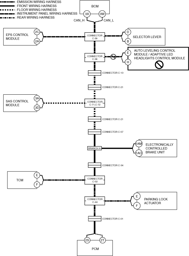
A
Possible cause
System wiring diagram
a30zzw00005411
|
Inspection item
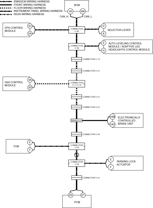
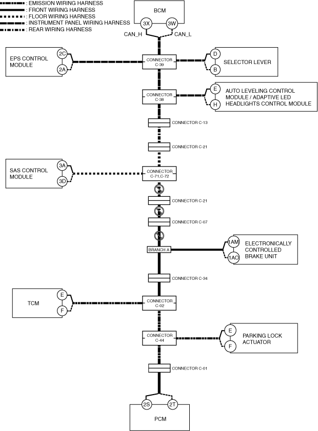
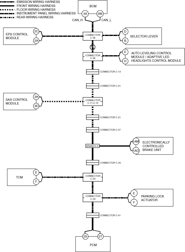
B
Possible cause
System wiring diagram
a30zzw00005412
|
Inspection item
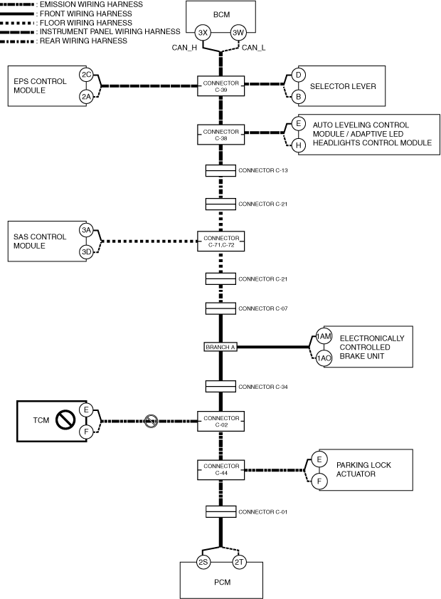
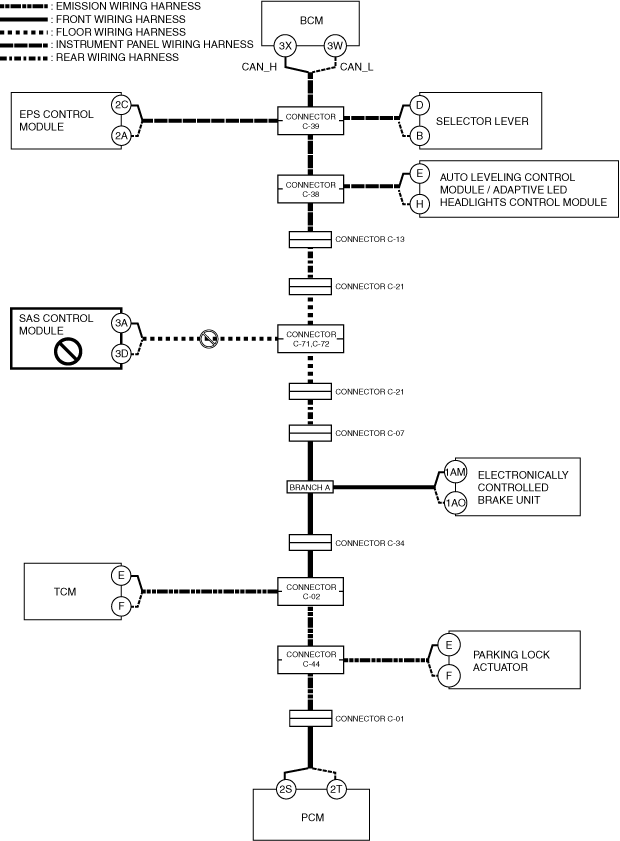
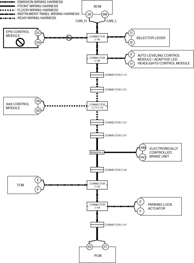
C
Possible cause
System wiring diagram
a30zzw00005413
|
Inspection item
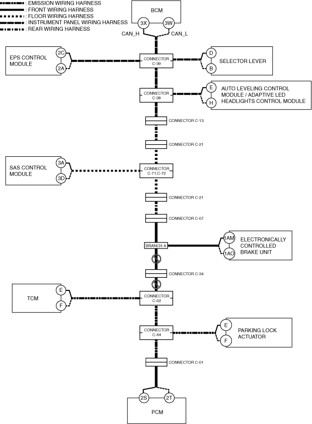
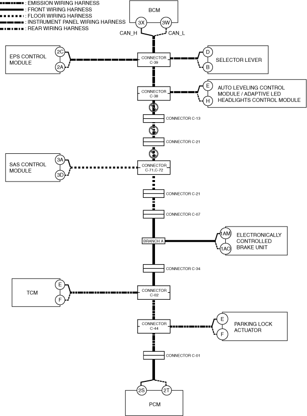
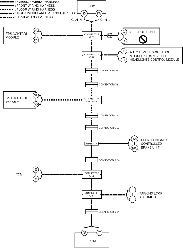
D
Possible cause
System wiring diagram
a30zzw00005414
|
Inspection item
E
Possible cause
System wiring diagram
a30zzw00005415
|
Inspection item
F
Possible cause
System wiring diagram
a30zzw00005416
|
Inspection item
G
Possible cause
System wiring diagram
a30zzw00005417
|
Inspection item
H
Possible cause
System wiring diagram
a30zzw00005418
|
Inspection item
I
Possible cause
System wiring diagram
a30zzw00005419
|
Inspection item
J
Possible cause
System wiring diagram
a30zzw00005420
|
Inspection item
K
Possible cause
System wiring diagram
a30zzw00005421
|
Inspection item
L
Possible cause
System wiring diagram
a30zzw00005422
|
Inspection item
M
Possible cause
System wiring diagram
a30zzw00005423
|
Inspection item
N
Possible cause
System wiring diagram
a30zzw00005424
|
Inspection item