DETERMINING OPEN CIRCUIT LOCATION (CAN-BUS No.2)
id100200002100
-
Caution
-
• If the malfunctioning part is detected in the communication line, before disconnecting the related connector for inspection, press the connector in the connection direction to verify that there is no looseness or disconnection.
• When disconnecting the connector, verify that there is no damage, deformation, or corrosion of the connector terminals.
1. Verify the CAN system-related module DTCs and the module displayed in red or blue on the M-MDS screen.
2. Apply the communication error DTC and the module displayed in red or blue to the DTC output pattern and malfunctioning location, and select the possible cause for the diagnostic result and the reference for the inspection item. (See DTC Output Pattern And Malfunctioning Location.)
-
Note
-
• The open circuit location can be determined by the DTC indicated in the DTC output pattern and malfunctioning location chart. DTCs not listed in the chart are not used for the determination of the open circuit location. (See
DTC Output Pattern And Malfunctioning Location.)
• The module may be displayed in red or blue on the M-MDS screen even if there is no malfunction depending on the vehicle specification.
3. Inspect the possible cause and inspection item of the applicable malfunctioning part.
DTC Output Pattern And Malfunctioning Location
Cross (×): Communication error-related DTC
|
M-MDS display
|
DTC
|
DTC output pattern and malfunctioning location
|
|
DTC output module
|
|
PCM
|
U0100:00
|
|
|
|
|
|
|
|
|
|
|
|
|
|
|
U0103:00
|
|
|
|
×
|
|
|
|
|
|
|
|
|
|
|
U0121:00
|
|
|
|
|
|
×
|
|
|
|
|
|
|
|
|
U0129:00
|
|
|
|
|
|
×
|
|
|
|
|
|
|
|
|
U0131:00
|
|
|
|
|
|
|
|
|
|
|
|
|
|
|
U0140:00
|
|
|
|
|
|
|
|
|
|
|
|
|
×
|
|
U0151:00
|
|
|
|
|
|
|
|
|
|
|
|
|
|
|
U0155:00
|
|
|
|
|
|
|
|
|
|
|
|
|
|
|
U0164:00
|
|
|
|
|
|
|
|
|
|
|
|
|
|
|
U01BA:00
|
|
|
|
|
|
|
|
|
|
×
|
|
|
|
|
U0291:00
|
|
|
|
×
|
|
|
|
|
|
|
|
|
|
|
U102D:00
|
|
|
|
|
|
|
|
|
|
×
|
|
|
|
|
U2121:00
|
|
|
|
|
|
|
|
|
|
|
|
|
|
|
U212E:00
|
|
|
|
|
|
|
|
|
|
|
|
|
|
|
U2131:00
|
|
|
|
|
|
|
|
|
|
|
|
|
|
|
U2133:00
|
|
|
|
|
|
|
|
|
|
|
|
|
|
|
EPS control module
|
U0100:00
|
×
|
|
×
|
|
×
|
|
×
|
|
×
|
|
×
|
|
×
|
|
U0121:00
|
|
|
|
|
|
×
|
×
|
|
×
|
|
×
|
|
×
|
|
U0140:00
|
|
|
|
|
|
|
|
|
|
|
|
|
×
|
|
U2121:00
|
|
|
|
|
|
|
|
|
|
|
|
|
|
|
Electronically controlled brake unit
|
U0100:00
|
×
|
|
×
|
|
×
|
|
|
|
|
|
|
|
|
|
U0101:00
|
|
|
|
|
|
|
|
|
|
|
|
|
|
|
U0131:00
|
|
|
|
|
|
|
|
|
|
|
|
|
|
|
U0140:00
|
|
|
|
|
|
|
|
|
|
|
|
|
×
|
|
U0151:00
|
|
|
|
|
|
|
|
|
|
|
|
|
|
|
U0155:00
|
|
|
|
|
|
|
|
|
|
|
|
|
|
|
U0164:00
|
|
|
|
|
|
|
|
|
|
|
|
|
|
|
U2121:00
|
|
|
|
|
|
|
|
|
|
|
|
|
|
|
U212E:00
|
|
|
|
|
|
|
|
|
|
|
|
|
|
|
U2131:00
|
|
|
|
|
|
|
|
|
|
|
|
|
|
|
Vehicle control module (VCM)
|
U0100:00
|
×
|
|
×
|
|
×
|
|
×
|
|
×
|
|
×
|
|
×
|
|
U0101:00
|
|
|
|
|
|
|
|
|
|
|
|
|
|
|
U0121:00
|
|
|
|
|
|
×
|
×
|
|
×
|
|
×
|
|
×
|
|
U0126:00
|
|
|
|
|
|
|
|
|
|
|
|
|
|
|
U0131:00
|
|
|
|
|
|
|
|
|
|
|
|
|
|
|
U0140:00
|
|
|
|
|
|
|
|
|
|
|
|
|
×
|
|
U0151:00
|
|
|
|
|
|
|
|
|
|
|
|
|
|
|
U0155:00
|
|
|
|
|
|
|
|
|
|
|
|
|
|
|
U0156:00
|
|
|
|
|
|
|
|
|
|
|
|
|
|
|
U0164:00
|
|
|
|
|
|
|
|
|
|
|
|
|
|
|
U2120:00
|
|
|
|
|
|
|
|
|
|
|
|
|
|
|
U2122:00
|
|
|
|
|
|
|
|
|
|
|
|
|
|
|
U2123:00
|
|
|
|
|
|
|
|
|
|
|
|
|
|
|
U2125:00
|
|
|
|
|
|
|
|
|
|
|
|
|
|
|
U2126:00
|
|
|
|
|
|
|
|
|
|
|
|
|
|
|
U212E:00
|
|
|
|
|
|
|
|
|
|
|
|
|
|
|
U2131:00
|
|
|
|
|
|
|
|
|
|
|
|
|
|
|
U2132:00
|
|
|
|
|
|
|
|
|
|
|
|
|
|
|
U2133:00
|
|
|
|
|
|
|
|
|
|
|
|
|
|
|
U2139:00
|
|
|
|
|
|
|
|
|
|
|
|
|
|
|
U213A:00
|
|
|
|
|
|
|
|
|
|
|
|
|
|
|
Body control module (BCM)
|
U0100:00
|
×
|
|
×
|
|
×
|
|
×
|
|
×
|
|
×
|
|
×
|
|
U0101:00
|
|
|
|
|
|
|
|
|
|
|
|
|
|
|
U0103:00
|
|
|
|
×
|
|
|
|
|
|
|
|
|
|
|
U0103:87
|
|
|
|
×
|
|
|
|
|
|
|
|
|
|
|
U0111:00
|
|
×
|
×
|
|
×
|
|
×
|
|
×
|
|
×
|
|
×
|
|
U0115:00
|
×
|
|
×
|
|
×
|
|
×
|
|
×
|
|
×
|
|
×
|
|
U0120:00
|
|
|
|
|
|
|
|
|
|
|
|
×
|
×
|
|
U0121:00
|
|
|
|
|
|
×
|
×
|
|
×
|
|
×
|
|
×
|
|
U0121:87
|
|
|
|
|
|
×
|
×
|
|
×
|
|
×
|
|
×
|
|
U0126:00
|
|
|
|
|
|
|
|
|
|
|
|
|
|
|
U0131:00
|
|
|
|
|
|
|
|
|
|
|
|
|
|
|
U0151:00
|
|
|
|
|
|
|
|
|
|
|
|
|
|
|
U0155:00
|
|
|
|
|
|
|
|
|
|
|
|
|
|
|
U0156:00
|
|
|
|
|
|
|
|
|
|
|
|
|
|
|
U0158:00
|
|
|
|
|
|
|
|
|
|
|
|
|
|
|
U0164:00
|
|
|
|
|
|
|
|
|
|
|
|
|
|
|
U0182:00
|
|
|
|
|
|
|
|
|
|
|
|
|
|
|
U01BA:00
|
|
|
|
|
|
|
|
|
|
×
|
|
|
|
|
U0316:82
|
|
|
|
|
|
|
|
|
|
|
|
|
|
|
U2121:49
|
|
|
|
|
|
|
|
|
|
|
|
|
|
|
U212A:00
|
|
|
|
|
|
|
|
|
|
|
|
|
|
|
U212D:00
|
|
|
|
|
|
|
|
|
|
|
|
|
|
|
U212E:00
|
|
|
|
|
|
|
|
|
|
|
|
|
|
|
U2130:00
|
|
|
|
|
|
|
|
×
|
×
|
|
×
|
|
×
|
|
U2131:00
|
|
|
|
|
|
|
|
|
|
|
|
|
|
|
U2133:00
|
|
|
|
|
|
|
|
|
|
|
|
|
|
|
U213A:00
|
|
|
|
|
|
|
|
|
|
|
|
|
|
|
U213B:00
|
|
|
|
|
|
|
|
|
|
|
|
|
|
|
U213C:00
|
|
|
|
|
|
×
|
×
|
|
×
|
|
×
|
|
×
|
|
Connectivity master unit (CMU)
|
U0101:00
|
|
|
|
|
|
|
|
|
|
|
|
|
|
|
U0131:00
|
|
|
|
|
|
|
|
|
|
|
|
|
|
|
U0140:00
|
|
|
|
|
|
|
|
|
|
|
|
|
×
|
|
U0151:00
|
|
|
|
|
|
|
|
|
|
|
|
|
|
|
U0155:00
|
|
|
|
|
|
|
|
|
|
|
|
|
|
|
U2121:00
|
|
|
|
|
|
|
|
|
|
|
|
|
|
|
U213C:00
|
|
|
|
|
|
×
|
×
|
|
×
|
|
×
|
|
×
|
|
U213E:00
|
×
|
|
×
|
|
×
|
|
×
|
|
×
|
|
×
|
|
×
|
|
Auto leveling control module
|
U0122:87
|
|
|
|
|
|
×
|
×
|
|
×
|
|
×
|
|
×
|
|
U212A:87
|
|
|
|
|
|
|
|
|
|
|
|
|
|
|
U212B:87
|
|
|
|
|
|
|
|
|
|
|
|
|
×
|
|
U212D:87
|
|
|
|
|
|
|
|
|
|
|
|
|
|
|
Adaptive LED headlights control module
|
U0122:87
|
|
|
|
|
|
×
|
×
|
|
×
|
|
×
|
|
×
|
|
U0126:87
|
|
|
|
|
|
|
|
|
|
|
|
|
|
|
U0155:87
|
|
|
|
|
|
|
|
|
|
|
|
|
|
|
U2121:87
|
|
|
|
|
|
|
|
|
|
|
|
|
|
|
U212A:87
|
|
|
|
|
|
|
|
|
|
|
|
|
|
|
U212B:87
|
|
|
|
|
|
|
|
|
|
|
|
|
×
|
|
U212D:87
|
|
|
|
|
|
|
|
|
|
|
|
|
|
|
Dash-electrical supply unit
|
U0100:00
|
×
|
|
×
|
|
×
|
|
×
|
|
×
|
|
×
|
|
×
|
|
U0121:00
|
|
|
|
|
|
×
|
×
|
|
×
|
|
×
|
|
×
|
|
U0151:00
|
|
|
|
|
|
|
|
|
|
|
|
|
|
|
U212B:00
|
|
|
|
|
|
|
|
|
|
|
|
|
×
|
|
U212E:00
|
|
|
|
|
|
|
|
|
|
|
|
|
|
|
U2131:00
|
|
|
|
|
|
|
|
|
|
|
|
|
|
|
U2133:00
|
|
|
|
|
|
|
|
|
|
|
|
|
|
|
U213A:00
|
|
|
|
|
|
|
|
|
|
|
|
|
|
|
SAS control module
|
U0140:00
|
|
|
|
|
|
|
|
|
|
|
|
|
×
|
|
U0155:00
|
|
|
|
|
|
|
|
|
|
|
|
|
|
|
U0156:00
|
|
|
|
|
|
|
|
|
|
|
|
|
|
|
TCM [ET6A-EL, ET6AX-EL]
|
U0100:00
|
×
|
|
×
|
|
×
|
|
×
|
|
×
|
|
×
|
|
×
|
|
U0121:00
|
|
|
|
|
|
×
|
×
|
|
×
|
|
×
|
|
×
|
|
U0131:00
|
|
|
|
|
|
|
|
|
|
|
|
|
|
|
U0140:00
|
|
|
|
|
|
|
|
|
|
|
|
|
×
|
|
U0155:00
|
|
|
|
|
|
|
|
|
|
|
|
|
|
|
U212C:00
|
|
|
|
|
|
|
|
|
|
|
|
|
|
|
Integrated starter generator (ISG)
|
U0100:00
|
×
|
|
×
|
|
×
|
|
×
|
|
×
|
|
×
|
|
|
|
Mazda M Hybrid battery
|
U0100:00
|
×
|
|
|
|
|
|
|
|
|
|
|
|
|
|
DC-DC Converter (Mazda M Hybrid)
|
U0100:00
|
×
|
|
×
|
|
×
|
|
×
|
|
|
|
|
|
|
|
U212B:00
|
|
|
|
|
|
|
|
|
|
|
|
|
×
|
|
Selector lever
|
U0100:00
|
×
|
|
×
|
|
|
|
|
|
|
|
|
|
|
|
U0101:00
|
|
|
|
|
|
|
|
|
|
|
|
|
|
|
U0121:00
|
|
|
|
|
|
×
|
|
|
|
|
|
|
|
|
U0140:00
|
|
|
|
|
|
|
|
|
|
|
|
|
×
|
|
U212B:00
|
|
|
|
|
|
|
|
|
|
|
|
|
×
|
|
Parking lock actuator
|
U0100:00
|
×
|
|
|
|
|
|
|
|
|
|
|
|
|
|
U0115:00
|
×
|
|
|
|
|
|
|
|
|
|
|
|
|
|
U0100:41
|
×
|
|
|
|
|
|
|
|
|
|
|
|
|
|
U0100:82
|
×
|
|
|
|
|
|
|
|
|
|
|
|
|
|
M-MDS display module
|
Module displayed in red or blue
|
|
PCM
|
×
|
|
×
|
|
×
|
|
×
|
|
×
|
|
×
|
|
×
|
|
Mazda M Hybrid battery
|
|
×
|
×
|
|
×
|
|
×
|
|
×
|
|
×
|
|
×
|
|
Selector lever
|
|
|
|
×
|
×
|
|
×
|
|
×
|
|
×
|
|
×
|
|
Electronically controlled brake unit
|
|
|
|
|
|
×
|
×
|
|
×
|
|
×
|
|
×
|
|
DC-DC converter (Mazda M Hybrid)
|
|
|
|
|
|
|
|
×
|
×
|
|
×
|
|
×
|
|
Parking lock actuator
|
|
|
|
|
|
|
|
|
|
×
|
×
|
|
×
|
|
Integrated starter generator (ISG)
|
|
|
|
|
|
|
|
|
|
|
|
×
|
×
|
|
Diagnostic result
|
|
Possible cause and inspection item
|
|
|
|
|
|
|
|
|
|
|
|
|
|
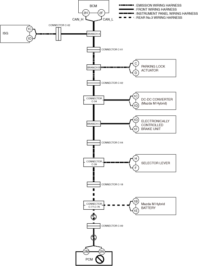
A
Possible cause
-
• Connector terminal disconnection, poor contact, damage, deformation, corrosion
• PCM power supply voltage or body ground malfunction
• Open circuit in wiring harness between PCM and connector C-09
• Open circuit in wiring harness between connector C-09 and connectors C-77, C-76
• Connector C-09 malfunction
• Connectors C-77, C-76 malfunction
• PCM malfunction
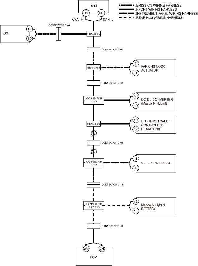
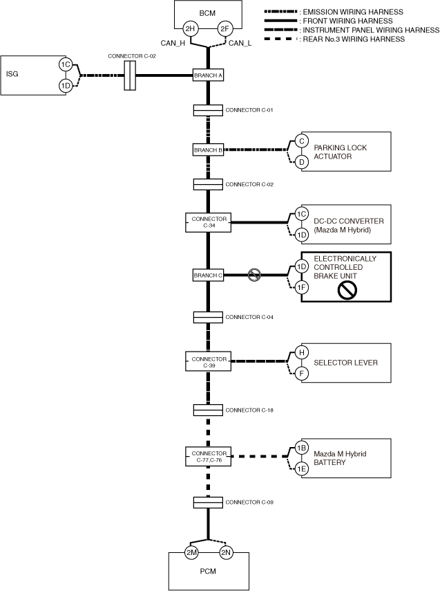
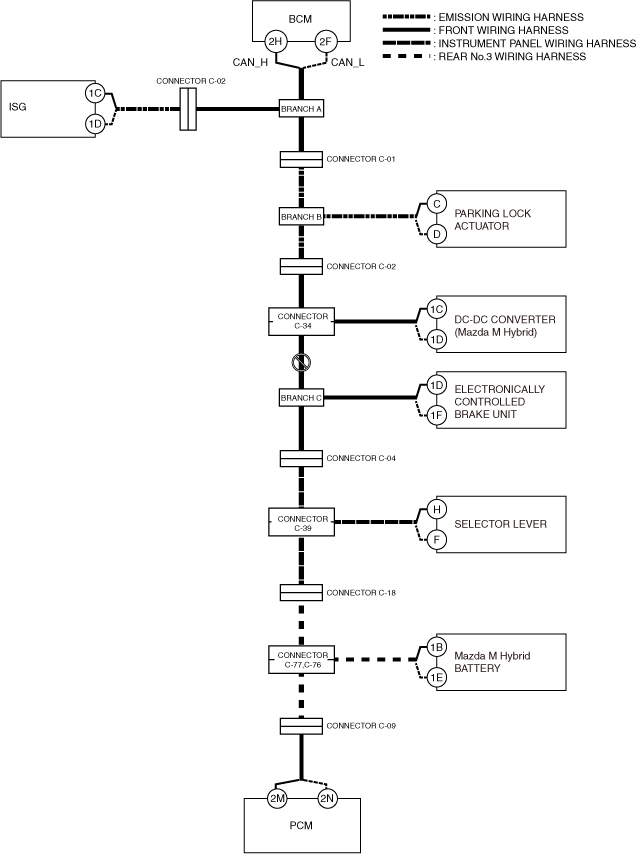
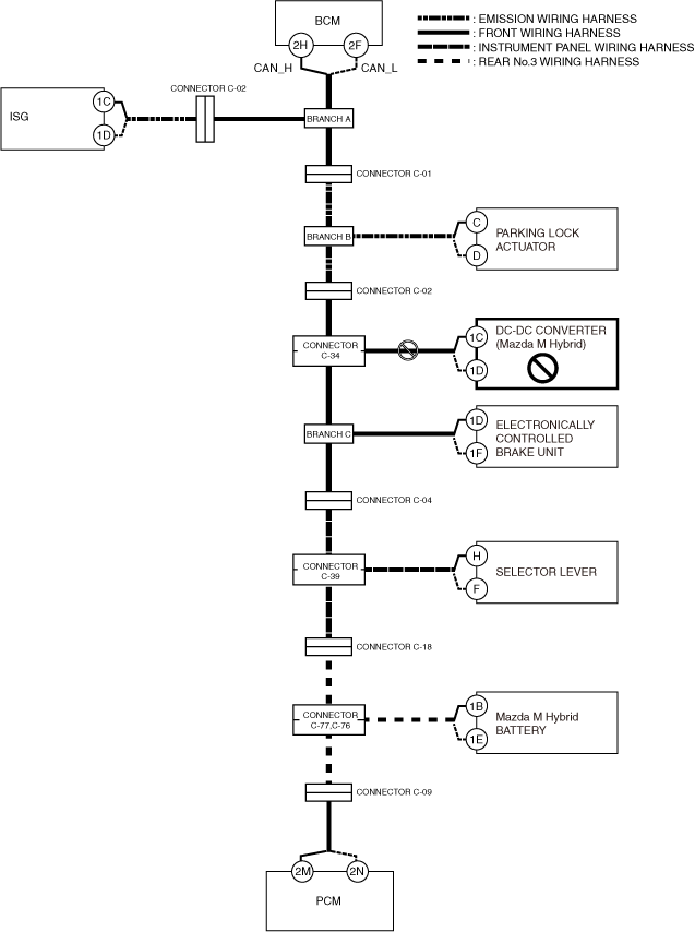
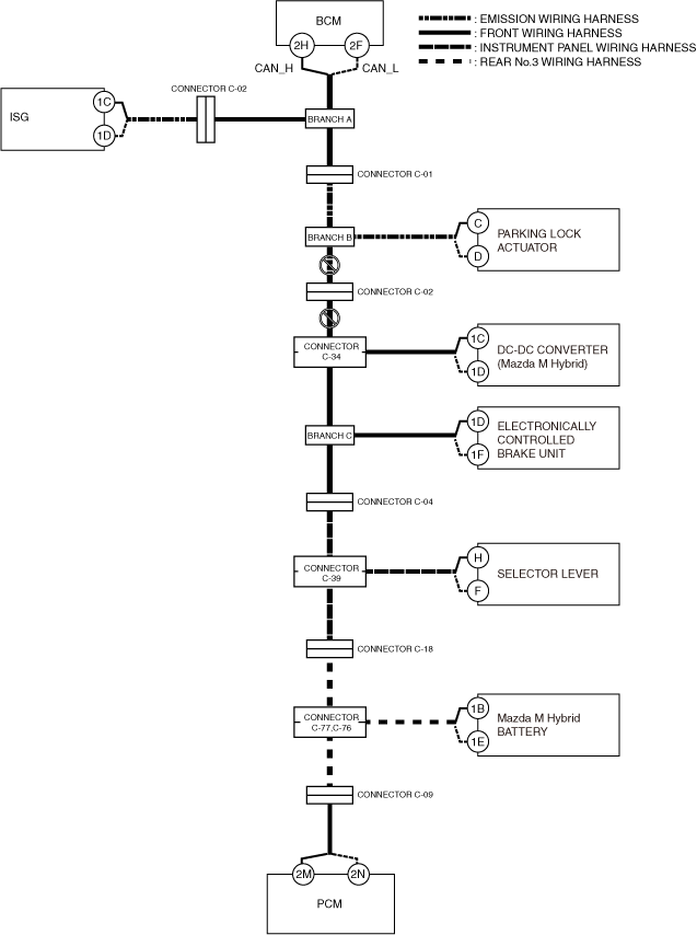
System wiring diagram
Inspection item
-
• PCM power supply voltage-related wiring harness and fuse
• PCM body ground related wiring harness
• PCM connector
• Connector C-09
• Connectors C-77, C-76
• Wiring harness between PCM terminal 2M and connector C-09
• Wiring harness between PCM terminal 2N and connector C-09
• Wiring harness between connector C-09 and connectors C-77, C-76
• PCM
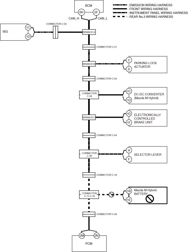
B
Possible cause
-
• Connector terminal disconnection, poor contact, damage, deformation, corrosion
• Mazda M Hybrid battery power supply voltage or body ground malfunction
• Open circuit in wiring harness between Mazda M Hybrid battery and connectors C-77, C-76
• Connectors C-77, C-76 malfunction
• Mazda M Hybrid battery malfunction
System wiring diagram
Inspection item
-
• Mazda M Hybrid battery power supply voltage-related wiring harness and fuse
• Mazda M Hybrid battery body ground related wiring harness
• Mazda M Hybrid battery connector
• Connectors C-77, C-76
• Wiring harness between Mazda M Hybrid battery terminal 1B and connector C-77
• Wiring harness between Mazda M Hybrid battery terminal 1E and connector C-76
• Mazda M Hybrid battery
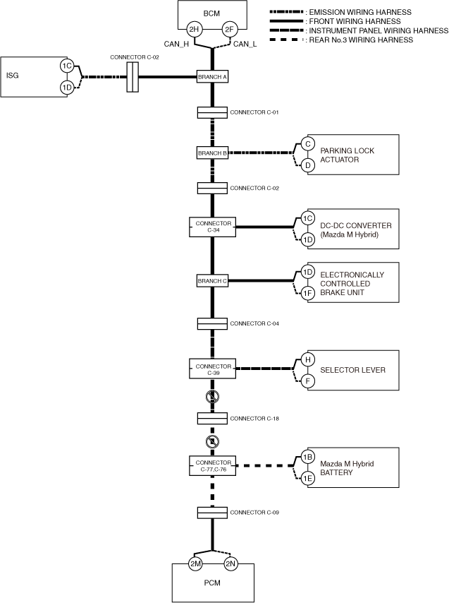
C
Possible cause
-
• Connector terminal disconnection, poor contact, damage, deformation, corrosion
• Open circuit in wiring harness between connectors C-77, C-76 and connector C-18
• Open circuit in wiring harness between connector C-18 and connector C-39
• Connector C-18 malfunction
• Connector C-39 malfunction
• Connectors C-77, C-76 malfunction
System wiring diagram
Inspection item
-
• Wiring harness between connectors C-77, C-76 and connector C-18
• Wiring harness between connector C-18 and connector C-39
• Connectors C-77, C-76
• Connector C-18
• Connector C-39
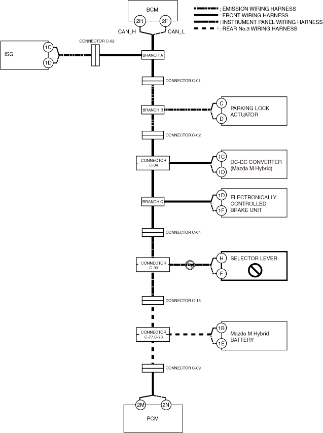
D
Possible cause
-
• Connector terminal disconnection, poor contact, damage, deformation, corrosion
• Selector lever power supply voltage or body ground malfunction
• Open circuit in wiring harness between selector lever and connector C-39
• Connector C-39 malfunction
• Selector lever malfunction
System wiring diagram
Inspection item
-
• Selector lever power supply voltage-related wiring harness and fuse
• Selector lever body ground related wiring harness
• Selector lever connector
• Connector C-39
• Wiring harness between selector lever terminal H and connector C-39
• Wiring harness between selector lever terminal F and connector C-39
• Selector lever
E
Possible cause
-
• Connector terminal disconnection, poor contact, damage, deformation, corrosion
• Open circuit in wiring harness between connector C-39 and connector C-04
• Open circuit in wiring harness between connector C-04 and branch C
• Connector C-39 malfunction
• Connector C-04 malfunction
System wiring diagram
Inspection item
-
• Connector C-39
• Connector C-04
• Wiring harness between connector C-39 and connector C-04
• Wiring harness between connector C-04 and connector branch C
F
Possible cause
-
• Connector terminal disconnection, poor contact, damage, deformation, corrosion
• Electronically controlled brake unit power supply voltage or body ground malfunction
• Open circuit in wiring harness between electronically controlled brake unit and branch C
• Electronically controlled brake unit malfunction
System wiring diagram
Inspection item
-
• Electronically controlled brake unit power supply voltage-related wiring harness and fuse
• Electronically controlled brake unit body ground related wiring harness
• Electronically controlled brake unit connector
• Wiring harness between electronically controlled brake unit terminal 1D and connector branch C
• Wiring harness between electronically controlled brake unit terminal 1F and connector branch C
• Electronically controlled brake unit
G
Possible cause
• Connector terminal disconnection, poor contact, damage, deformation, corrosion
• Open circuit in wiring harness between branch C and connector C-34
• Connector C-34 malfunction
System wiring diagram
Inspection item
-
• Connector C-34
• Wiring harness between branch C and connector C-34
H
Possible cause
-
• Connector terminal disconnection, poor contact, damage, deformation, corrosion
• DC-DC converter (Mazda M Hybrid) power supply voltage or body ground malfunction
• Open circuit in wiring harness between DC-DC converter (Mazda M Hybrid) and connectors C-34
• DC-DC converter (Mazda M Hybrid) malfunction
• Connector C-34 malfunction
System wiring diagram
Inspection item
-
• DC-DC converter (Mazda M Hybrid) power supply voltage-related wiring harness and fuse
• DC-DC converter (Mazda M Hybrid) body ground related wiring harness
• DC-DC converter (Mazda M Hybrid) connector
• Connector C-34
• Wiring harness between DC-DC converter (Mazda M Hybrid) terminal 1C and connector C-34
• Wiring harness between DC-DC converter (Mazda M Hybrid) terminal 1D and connector C-34
• DC-DC converter (Mazda M Hybrid)
I
Possible cause
-
• Connector terminal disconnection, poor contact, damage, deformation, corrosion
• Open circuit in wiring harness between connector C-34 and connector C-02
• Open circuit in wiring harness between connector C-02 and branch B
• Connector C-34 malfunction
• Connector C-02 malfunction
System wiring diagram
Inspection item
-
• Connector C-34
• Connector C-02
• Wiring harness between connector C-34 and connector C-02
• Wiring harness between connector C-02 and branch B
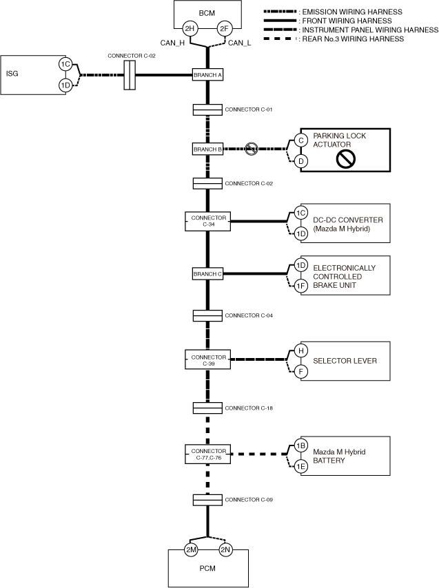
J
Possible cause
-
• Connector terminal disconnection, poor contact, damage, deformation, corrosion
• Parking lock actuator power supply voltage or body ground malfunction
• Open circuit in wiring harness between parking lock actuator and branch B
• Parking lock actuator malfunction
System wiring diagram
Inspection item
-
• Parking lock actuator power supply voltage-related wiring harness and fuse
• Parking lock actuator body ground related wiring harness
• Parking lock actuator connector
• Wiring harness between parking lock actuator terminal C and branch B
• Wiring harness between parking lock actuator terminal D and branch B
• Parking lock actuator
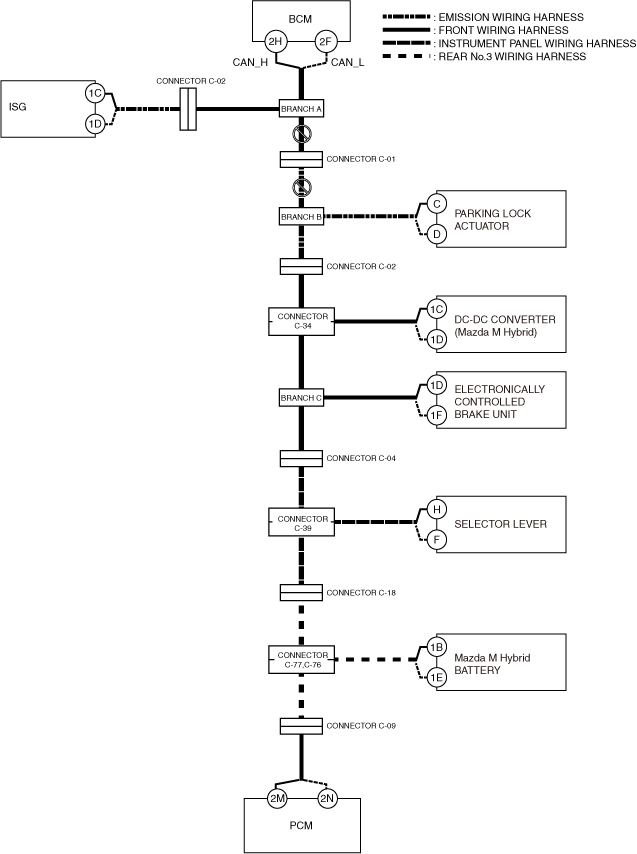
K
Possible cause
-
• Connector terminal disconnection, poor contact, damage, deformation, corrosion
• Open circuit in wiring harness between branch B and connector C-01
• Open circuit in wiring harness between connector C-01 and branch A
• Connector C-01 malfunction
System wiring diagram
Inspection item
-
• Connector C-01
• Wiring harness between branch B and connector C-01
• Wiring harness between connector C-01 and branch A
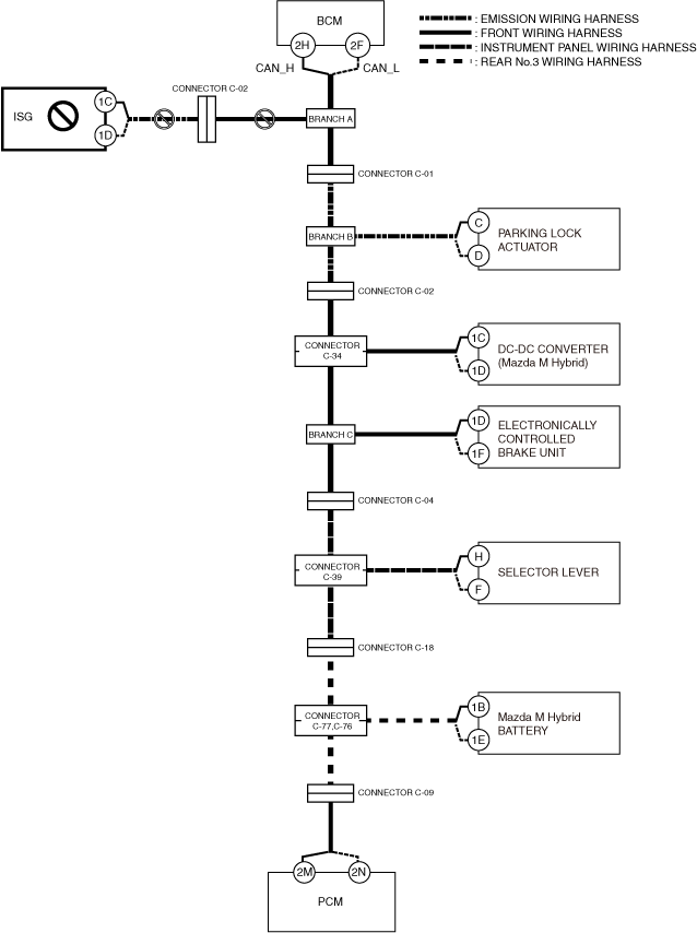
L
Possible cause
-
• Connector terminal disconnection, poor contact, damage, deformation, corrosion
• Integrated starter generator (ISG) power supply voltage or body ground malfunction
• Open circuit in wiring harness between integrated starter generator (ISG) and connector C-02
• Open circuit in wiring harness between connector C-02 and connector branch A
• Connector C-02 malfunction
• Integrated starter generator (ISG) malfunction
System wiring diagram
Inspection item
-
• Integrated starter generator (ISG) power supply voltage-related wiring harness and fuse
• Integrated starter generator (ISG) body ground related wiring harness
• Integrated starter generator (ISG) connector
• Connector C-02
• Wiring harness between integrated starter generator (ISG) terminal 1C and connector C-02
• Wiring harness between integrated starter generator (ISG) terminal 1D and connector C-02
• Wiring harness between connector C-02 and branch A
• Integrated starter generator (ISG)
M
Possible cause
-
• Connector terminal disconnection, poor contact, damage, deformation, corrosion
• Body control module (BCM) power supply voltage or body ground malfunction
• Open circuit in wiring harness between body control module (BCM) and branch A
• Body control module (BCM) malfunction
System wiring diagram
Inspection item
-
• Body control module (BCM) power supply voltage-related wiring harness and fuse
• Body control module (BCM) body ground related wiring harness
• Body control module (BCM) connector
• Wiring harness between body control module (BCM) terminal 2H and connector branch A
• Wiring harness between body control module (BCM) terminal 2F and connector branch A
• Body control module (BCM)