 |
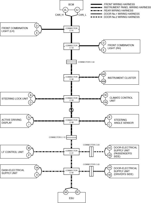
a30zzw00005440
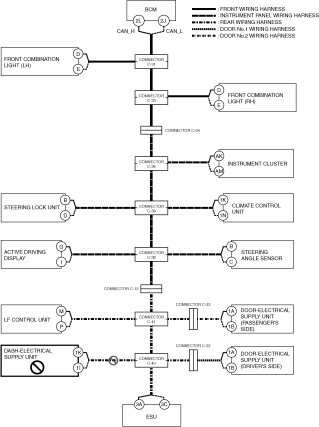
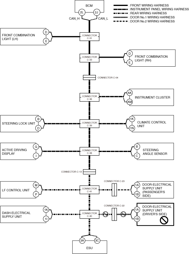
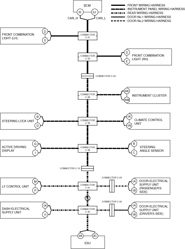
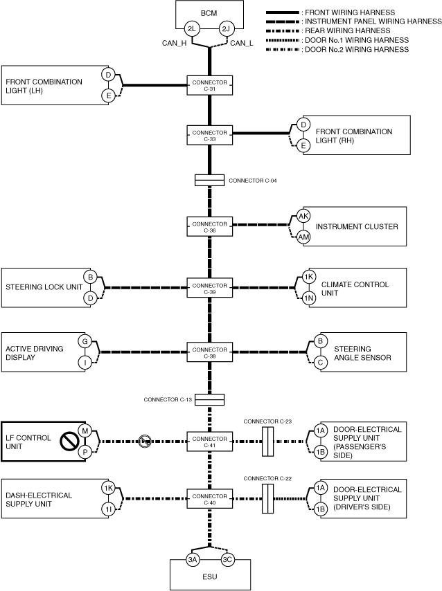
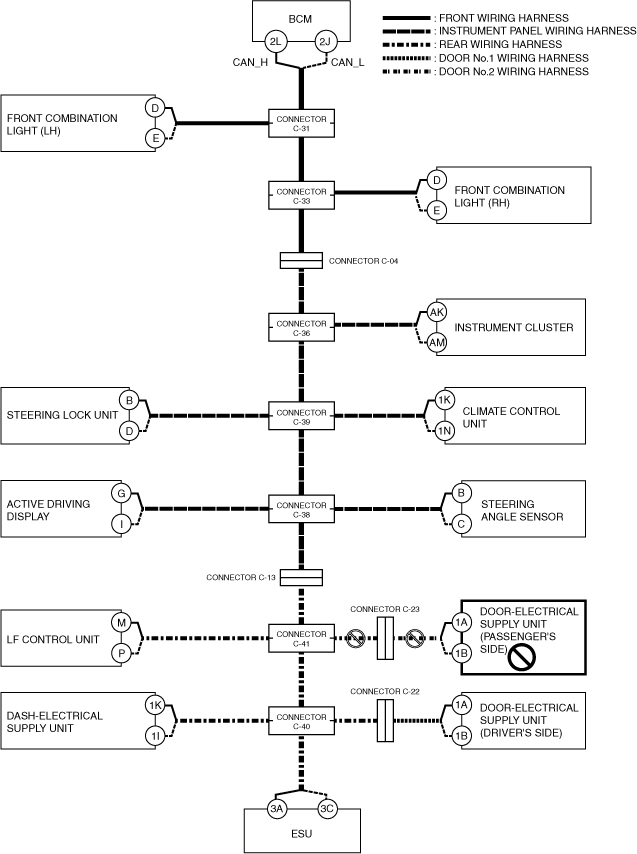
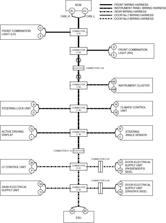
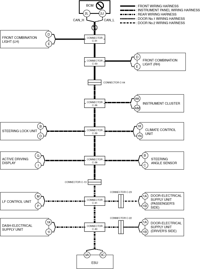
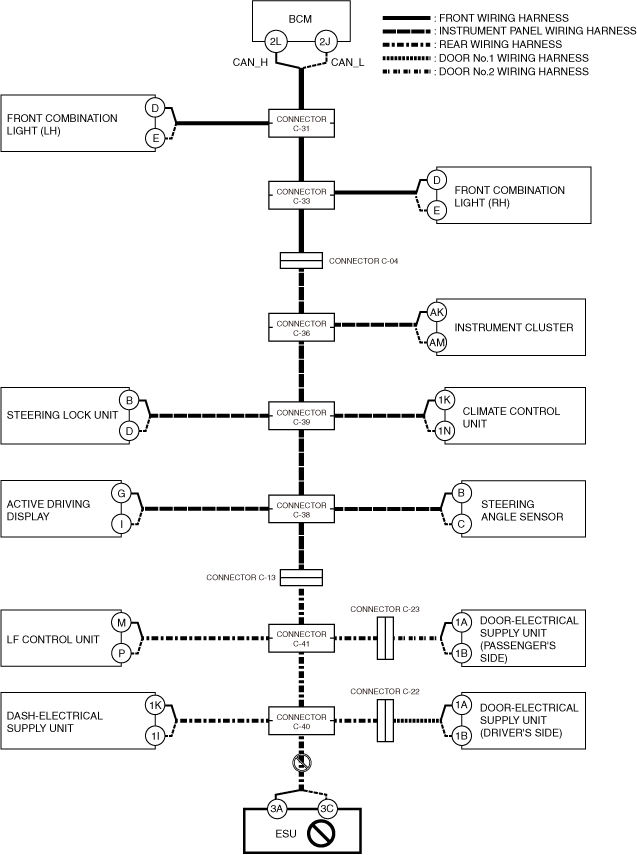
DETERMINING OPEN CIRCUIT LOCATION (CAN-BUS No.3)
id100200002500
1. Verify the CAN system-related module DTCs and the module displayed in red or blue on the M-MDS screen.
2. Apply the communication error DTC and the module displayed in red or blue to the DTC output pattern and malfunctioning location, and select the possible cause for the diagnostic result and the reference for the inspection item. (See DTC Output Pattern And Malfunctioning Location)
3. Inspect the possible cause and inspection item of the applicable malfunctioning part.
DTC Output Pattern And Malfunctioning Location
|
M-MDS display |
DTC |
DTC output pattern and malfunctioning location |
||||||||||||||||||
|---|---|---|---|---|---|---|---|---|---|---|---|---|---|---|---|---|---|---|---|---|
|
DTC output module |
||||||||||||||||||||
|
PCM
|
U0100:00
|
|||||||||||||||||||
|
U0103:00
|
||||||||||||||||||||
|
U0121:00
|
||||||||||||||||||||
|
U0129:00
|
||||||||||||||||||||
|
U0131:00
|
||||||||||||||||||||
|
U0140:00
|
×
|
|||||||||||||||||||
|
U0151:00
|
||||||||||||||||||||
|
U0155:00
|
×
|
×
|
×
|
×
|
||||||||||||||||
|
U0164:00
|
×
|
×
|
×
|
×
|
×
|
×
|
×
|
×
|
||||||||||||
|
U01BA:00
|
||||||||||||||||||||
|
U0291:00
|
||||||||||||||||||||
|
U102D:00
|
||||||||||||||||||||
|
U2121:00
|
||||||||||||||||||||
|
U212E:00
|
×
|
×
|
×
|
×
|
×
|
×
|
×
|
|||||||||||||
|
U2131:00
|
×
|
×
|
×
|
×
|
×
|
×
|
×
|
×
|
||||||||||||
|
U2133:00
|
×
|
×
|
×
|
×
|
×
|
|||||||||||||||
|
EPS control module
|
U0100:00
|
|||||||||||||||||||
|
U0121:00
|
||||||||||||||||||||
|
U0140:00
|
×
|
|||||||||||||||||||
|
U2121:00
|
||||||||||||||||||||
|
Electronically controlled brake unit
|
U0100:00
|
|||||||||||||||||||
|
U0101:00
|
||||||||||||||||||||
|
U0131:00
|
||||||||||||||||||||
|
U0140:00
|
×
|
|||||||||||||||||||
|
U0151:00
|
||||||||||||||||||||
|
U0155:00
|
×
|
×
|
×
|
×
|
||||||||||||||||
|
U0164:00
|
×
|
×
|
×
|
×
|
×
|
×
|
×
|
×
|
||||||||||||
|
U2121:00
|
||||||||||||||||||||
|
U212E:00
|
×
|
×
|
×
|
×
|
×
|
×
|
×
|
|||||||||||||
|
U2131:00
|
×
|
×
|
×
|
×
|
×
|
×
|
×
|
×
|
||||||||||||
|
Vehicle control module (VCM)
|
U0100:00
|
|||||||||||||||||||
|
U0101:00
|
||||||||||||||||||||
|
U0121:00
|
||||||||||||||||||||
|
U0126:00
|
×
|
×
|
×
|
×
|
×
|
×
|
||||||||||||||
|
U0131:00
|
||||||||||||||||||||
|
U0140:00
|
×
|
|||||||||||||||||||
|
U0151:00
|
||||||||||||||||||||
|
U0155:00
|
×
|
×
|
×
|
×
|
||||||||||||||||
|
U0156:00
|
||||||||||||||||||||
|
U0164:00
|
×
|
×
|
×
|
×
|
×
|
×
|
×
|
×
|
||||||||||||
|
U2120:00
|
||||||||||||||||||||
|
U2122:00
|
||||||||||||||||||||
|
U2123:00
|
||||||||||||||||||||
|
U2125:00
|
||||||||||||||||||||
|
U2126:00
|
|
|||||||||||||||||||
|
U212E:00
|
×
|
×
|
×
|
×
|
×
|
×
|
×
|
|||||||||||||
|
U2131:00
|
×
|
×
|
×
|
×
|
×
|
×
|
×
|
×
|
||||||||||||
|
U2132:00
|
||||||||||||||||||||
|
U2133:00
|
×
|
×
|
×
|
×
|
×
|
|||||||||||||||
|
U2139:00
|
||||||||||||||||||||
|
U213A:00
|
×
|
×
|
×
|
×
|
×
|
×
|
×
|
×
|
||||||||||||
|
Body control module (BCM)
|
U0100:00
|
|||||||||||||||||||
|
U0101:00
|
||||||||||||||||||||
|
U0103:00
|
||||||||||||||||||||
|
U0103:87
|
||||||||||||||||||||
|
U0111:00
|
||||||||||||||||||||
|
U0115:00
|
||||||||||||||||||||
|
U0120:00
|
||||||||||||||||||||
|
U0121:00
|
||||||||||||||||||||
|
U0121:87
|
||||||||||||||||||||
|
U0126:00
|
×
|
×
|
×
|
×
|
×
|
×
|
||||||||||||||
|
U0131:00
|
||||||||||||||||||||
|
U0151:00
|
||||||||||||||||||||
|
U0155:00
|
×
|
×
|
×
|
×
|
||||||||||||||||
|
U0156:00
|
||||||||||||||||||||
|
U0158:00
|
×
|
×
|
×
|
×
|
×
|
×
|
||||||||||||||
|
U0164:00
|
×
|
×
|
×
|
×
|
×
|
×
|
×
|
×
|
||||||||||||
|
U0182:00
|
||||||||||||||||||||
|
U01BA:00
|
||||||||||||||||||||
|
U0316:82
|
||||||||||||||||||||
|
U2121:49
|
||||||||||||||||||||
|
U212A:00
|
×
|
×
|
||||||||||||||||||
|
U212D:00
|
×
|
×
|
×
|
|||||||||||||||||
|
U212E:00
|
×
|
×
|
×
|
×
|
×
|
×
|
×
|
|||||||||||||
|
U2130:00
|
||||||||||||||||||||
|
U2131:00
|
×
|
×
|
×
|
×
|
×
|
×
|
×
|
×
|
||||||||||||
|
U2133:00
|
×
|
×
|
×
|
×
|
×
|
|||||||||||||||
|
U213A:00
|
×
|
×
|
×
|
×
|
×
|
×
|
×
|
×
|
||||||||||||
|
U213B:00
|
×
|
×
|
×
|
×
|
×
|
×
|
×
|
|||||||||||||
|
U213C:00
|
||||||||||||||||||||
|
Connectivity master unit (CMU)
|
U0101:00
|
|||||||||||||||||||
|
U0131:00
|
||||||||||||||||||||
|
U0140:00
|
×
|
|||||||||||||||||||
|
U0151:00
|
||||||||||||||||||||
|
U0155:00
|
×
|
×
|
×
|
×
|
||||||||||||||||
|
U2121:00
|
||||||||||||||||||||
|
U213C:00
|
||||||||||||||||||||
|
U213E:00
|
||||||||||||||||||||
|
Auto leveling control module
|
U0122:87
|
|||||||||||||||||||
|
U212A:87
|
×
|
×
|
||||||||||||||||||
|
U212B:87
|
×
|
|||||||||||||||||||
|
U212D:87
|
×
|
×
|
×
|
|||||||||||||||||
|
Adaptive LED headlights control module
|
U0122:87
|
|||||||||||||||||||
|
U0126:87
|
×
|
×
|
×
|
×
|
×
|
×
|
||||||||||||||
|
U0155:87
|
×
|
×
|
×
|
×
|
||||||||||||||||
|
U2121:87
|
||||||||||||||||||||
|
U212A:87
|
×
|
×
|
||||||||||||||||||
|
U212B:87
|
×
|
|||||||||||||||||||
|
U212D:87
|
×
|
×
|
×
|
|||||||||||||||||
|
Dash-electrical supply unit
|
U0100:00
|
|||||||||||||||||||
|
U0121:00
|
||||||||||||||||||||
|
U0151:00
|
||||||||||||||||||||
|
U212B:00
|
×
|
|||||||||||||||||||
|
U212E:00
|
×
|
|||||||||||||||||||
|
U2131:00
|
×
|
|||||||||||||||||||
|
U2133:00
|
×
|
|||||||||||||||||||
|
U213A:00
|
×
|
|||||||||||||||||||
|
SAS control module
|
U0140:00
|
×
|
||||||||||||||||||
|
U0155:00
|
×
|
×
|
×
|
×
|
||||||||||||||||
|
U0156:00
|
×
|
×
|
×
|
×
|
||||||||||||||||
|
TCM [ET6A-EL, ET6AX-EL]
|
U0100:00
|
|||||||||||||||||||
|
U0121:00
|
||||||||||||||||||||
|
U0131:00
|
||||||||||||||||||||
|
U0140:00
|
×
|
|||||||||||||||||||
|
U0155:00
|
×
|
×
|
×
|
×
|
||||||||||||||||
|
U212C:00
|
||||||||||||||||||||
|
Integrated starter generator (ISG)
|
U0100:00
|
|||||||||||||||||||
|
Mazda M Hybrid battery
|
U0100:00
|
|||||||||||||||||||
|
DC-DC Converter (Mazda M Hybrid)
|
U0100:00
|
|||||||||||||||||||
|
U212B:00
|
×
|
|||||||||||||||||||
|
Selector lever
|
U0100:00
|
|||||||||||||||||||
|
U0101:00
|
||||||||||||||||||||
|
U0121:00
|
||||||||||||||||||||
|
U0140:00
|
×
|
|||||||||||||||||||
|
U212B:00
|
×
|
|||||||||||||||||||
|
Parking lock actuator
|
U0100:00
|
|||||||||||||||||||
|
U0115:00
|
||||||||||||||||||||
|
U0100:41
|
||||||||||||||||||||
|
U0100:82
|
||||||||||||||||||||
|
M-MDS display module
|
Module displayed in red or blue
|
|||||||||||||||||||
|
Electrical supply unit (ESU)
|
×
|
×
|
×
|
×
|
×
|
×
|
×
|
×
|
||||||||||||
|
Dash-electrical supply unit
|
|
×
|
×
|
×
|
×
|
×
|
×
|
×
|
×
|
|||||||||||
|
Door-electrical supply unit (passenger's side)
|
|
×
|
×
|
×
|
×
|
×
|
×
|
×
|
×
|
|||||||||||
|
LF control unit
|
|
×
|
×
|
×
|
×
|
×
|
×
|
×
|
||||||||||||
|
Door-electrical supply unit (driver's side)
|
|
×
|
×
|
×
|
×
|
×
|
×
|
×
|
||||||||||||
|
Active driving display
|
|
×
|
×
|
×
|
×
|
×
|
×
|
|||||||||||||
|
Steering angle sensor
|
|
×
|
×
|
×
|
×
|
×
|
×
|
|||||||||||||
|
Steering lock unit
|
|
×
|
×
|
×
|
×
|
×
|
||||||||||||||
|
Climate control unit
|
|
×
|
×
|
×
|
×
|
×
|
||||||||||||||
|
Instrument cluster
|
|
×
|
×
|
×
|
×
|
|||||||||||||||
|
Heat pump control unit
|
|
×
|
×
|
×
|
||||||||||||||||
|
Front combination light (RH)
|
|
×
|
×
|
|||||||||||||||||
|
Front combination light (LH)
|
|
×
|
×
|
|||||||||||||||||
|
Body control module (BCM)
|
|
×
|
||||||||||||||||||
|
Diagnostic result
|
||||||||||||||||||||
|
Possible cause and inspection item
|
||||||||||||||||||||
A
Possible cause
System wiring diagram
a30zzw00005440
|
Inspection item
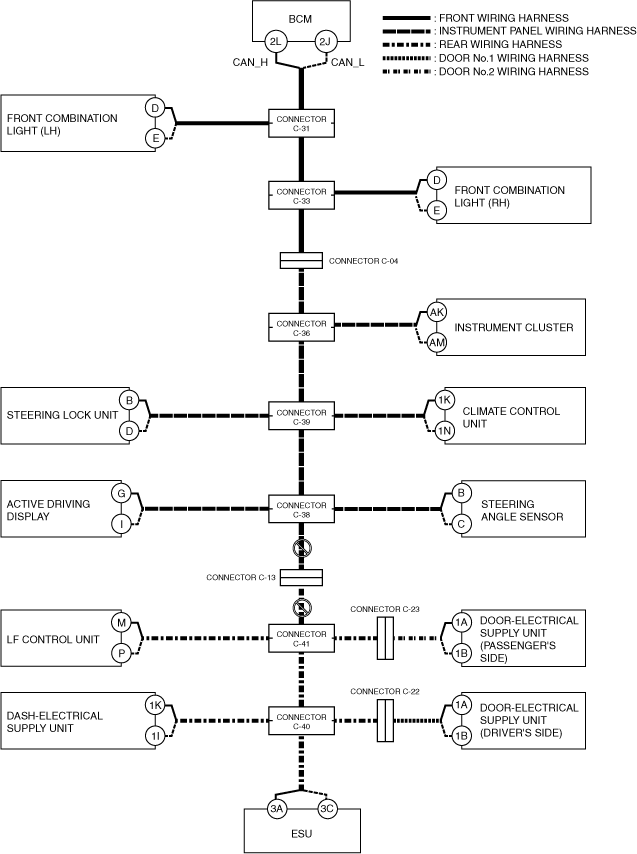
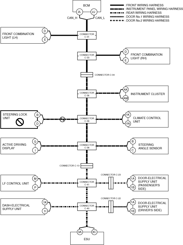
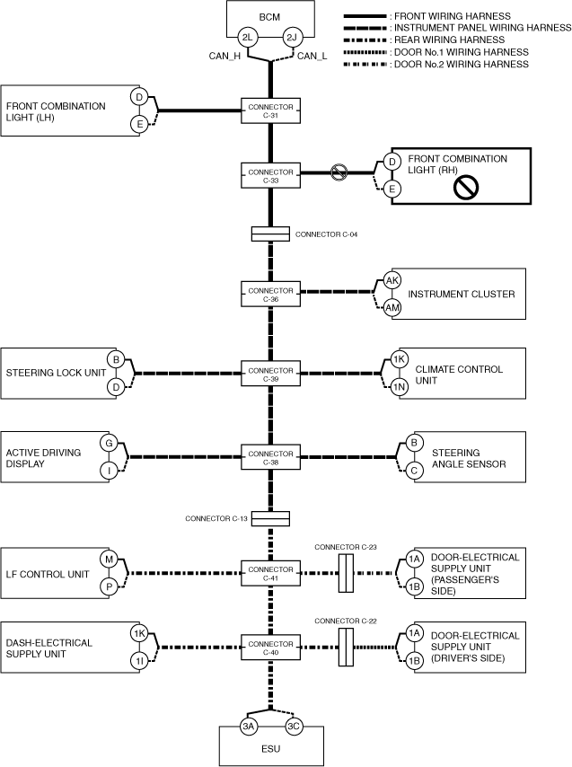
B
Possible cause
System wiring diagram
a30zzw00005441
|
Inspection item
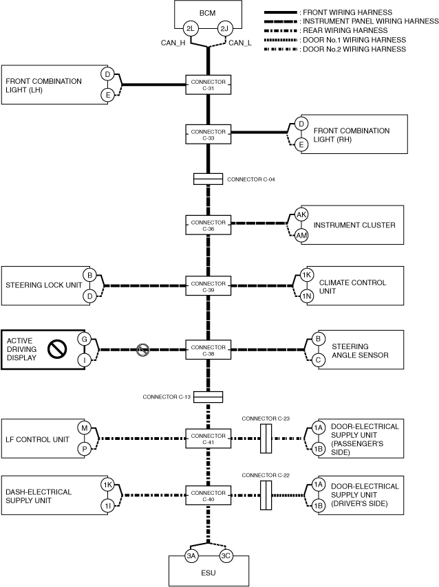
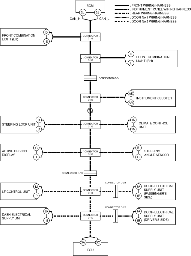
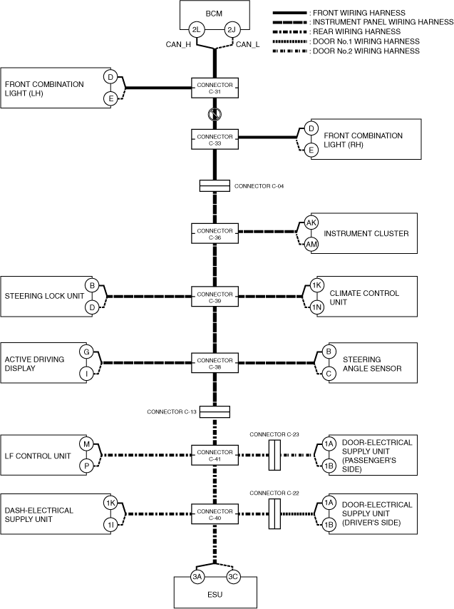
C
Possible cause
System wiring diagram
a30zzw00005442
|
Inspection item
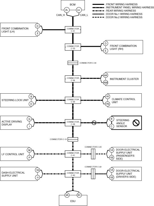
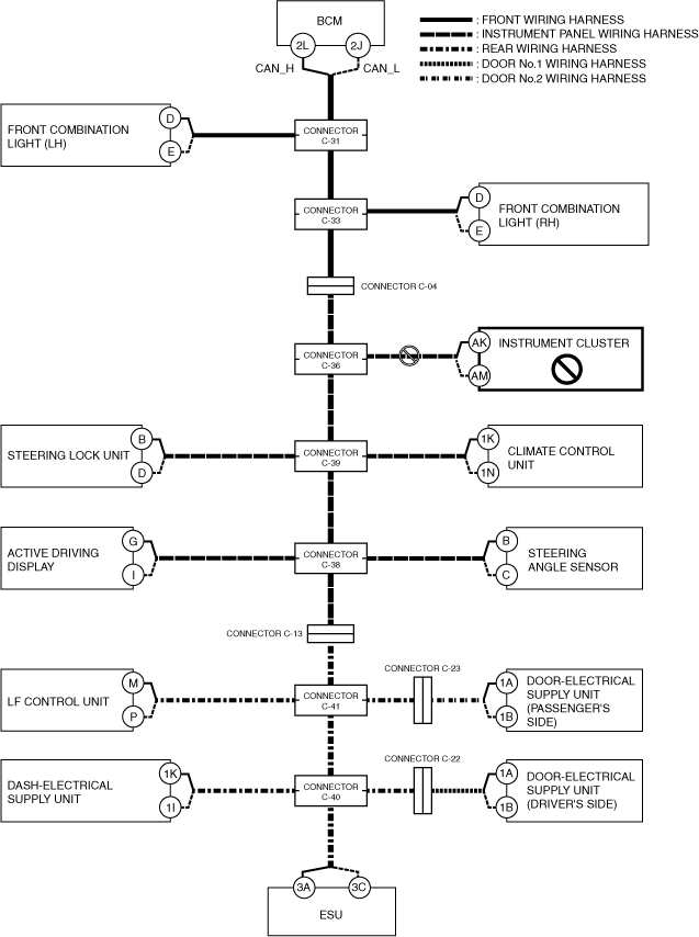
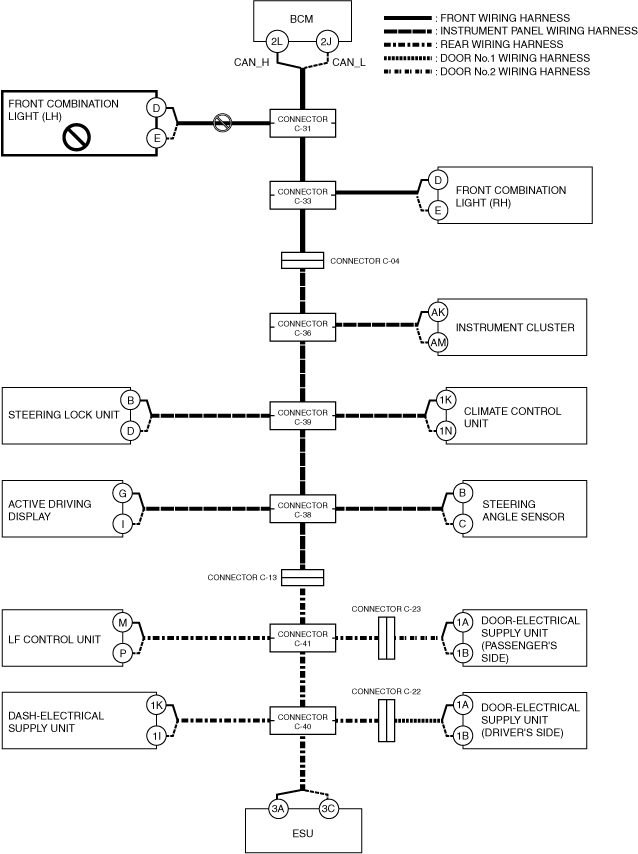
D
Possible cause
System wiring diagram
a30zzw00005443
|
Inspection item
E
Possible cause
System wiring diagram
a30zzw00005444
|
Inspection item
F
Possible cause
System wiring diagram
a30zzw00005445
|
Inspection item
G
Possible cause
System wiring diagram
a30zzw00005446
|
Inspection item
H
Possible cause
System wiring diagram
a30zzw00005447
|
Inspection item
I
Possible cause
System wiring diagram
a30zzw00005448
|
Inspection item
J
Possible cause
System wiring diagram
a30zzw00005449
|
Inspection item
K
Possible cause
System wiring diagram
a30zzw00005450
|
Inspection item
L
Possible cause
System wiring diagram
a30zzw00005451
|
Inspection item
M
Possible cause
System wiring diagram
a30zzw00005452
|
Inspection item
N
Possible cause
System wiring diagram
a30zzw00005453
|
Inspection item
O
Possible cause
System wiring diagram
a30zzw00005454
|
Inspection item
P
Possible cause
System wiring diagram
a30zzw00005455
|
Inspection item
Q
Possible cause
System wiring diagram
a30zzw00005456
|
Inspection item
R
Possible cause
System wiring diagram
a30zzw00005457
|
Inspection item
S
Possible cause
System wiring diagram
a30zzw00005458
|
Inspection item