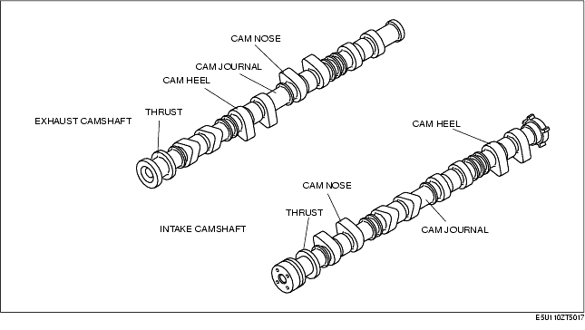
• The cast iron 5 axis-hole, which has great rigidity, has been adopted for the camshaft to insure higher reliability.
• The endplay of the camshaft is regulated at the rear of the No. 1 journal.
• The lubricating oil is supplied through the oil supply hole at each journal. Additionally the cam nose part is chill cast to improve the abrasion resistance and the width of cam hill part is shortened to reduce the weight.
• There is no camshaft sprocket positioning pin or key slot at the camshaft end. The camshaft sprocket is secured using tightening pressure of the installation bolts.
• There is an oil line, by which the oil is supplied to the variable valve timing actuator, located at the LF engine models intake camshaft (front of camshaft).
Camshaft Specification.
|
item
|
Specification
|
||||
|---|---|---|---|---|---|
|
L8
|
LF
|
||||
|
IN
|
EX
|
IN
|
EX
|
||
|
LIFT
|
(mm {in})
|
7.5 {0.29}
|
7.7 {0.30}
|
9.1 {0.35}
|
7.8 {0.30}
|
|
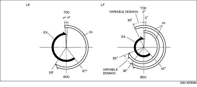
Overlap
|
(°)
|
8
|
5-35
|
||
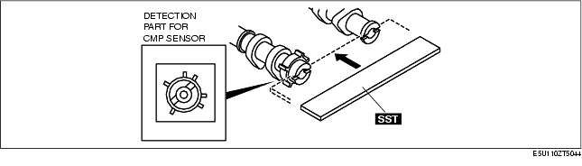
• The detection unit or the camshaft (CMP) sensor, which is integrated with the camshaft, is at the intake port side camshaft for L8 engine models.
• The detection unit (trigger plate) for the camshaft position (CMP) sensor is at the intake port side camshaft for LF engine models (with variable valve timing mechanism).
• LF engine models groove for securing the No.1 cylinder TDC for the camshaft, is provided at the rear of the intake and exhaust camshaft.