SOLENOID VALVE INSPECTION [SJ6A-EL]
id051311253200
-
Caution
-
• Water or foreign material entering the connector can cause poor connections or corrosion. Be sure that water or foreign material do not enter the connector when disconnecting it.
-
• Do not damage the terminals.
Resistance inspection (On-vehicle)
1. Remove the battery cover.
2. Disconnect the negative battery cable. (See BATTERY REMOVAL/INSTALLATION [L8, LF].)
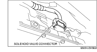
3. Disconnect the solenoid valve connector.
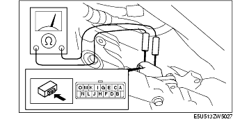
4. Measure the resistance between the following terminals.
-
• If there is any malfunction, inspect the coupler component.
-
• If the coupler component is normal, replace the control valve body. (See CONTROL VALVE BODY REMOVAL [SJ6A-EL].) (See CONTROL VALVE BODY INSTALLATION [SJ6A-EL].)
-
Solenoid valve resistance (ATF temperature: 20 °C {68 °F})
|
Terminals
|
Solenoid valve
|
Resistance (ohm)
|
|
O-GND
|
Shift solenoid A
|
5.0-5.6
|
|
N-GND
|
Shift solenoid B
|
5.0-5.6
|
|
M-GND
|
Shift solenoid C
|
5.0-5.6
|
|
L-GND
|
Shift solenoid D
|
5.0-5.6
|
|
K-GND
|
Shift solenoid E
|
5.0-5.6
|
|
E-F
|
Shift solenoid F
|
5.0-5.6
|
|
C-D
|
Shift solenoid G
|
5.0-5.6
|
|
I-J
|
Line pressure control solenoid
|
5.0-5.6
|
|
G-H
|
TCC control solenoid
|
5.0-5.6
|
5. Connect the solenoid valve connector.
6. Connect the negative battery cable. (See BATTERY REMOVAL/INSTALLATION [L8, LF].)
7. Install the battery cover.
Continuity Inspection (On-Vehicle Inspection)
-
Caution
-
• Water or foreign material entering the connector can cause a poor connection or corrosion. Be sure not to allow water or foreign material on the connector when disconnecting.
-
• Do not damage the terminals.
1. Remove the battery cover.
2. Disconnect the negative battery cable. (See BATTERY REMOVAL/INSTALLATION [L8, LF].)
3. Disconnect the solenoid valve connector.
4. Verify that there is no continuity between coupler component terminals C, D, E, F, G, H, I, J and GND.
-
• If there is any malfunction, inspect the coupler component.
-
• If the coupler component is normal, replace the control valve body. (See CONTROL VALVE BODY REMOVAL [SJ6A-EL].) (See CONTROL VALVE BODY INSTALLATION [SJ6A-EL].)
5. Connect the solenoid valve connector.
6. Connect the negative battery cable. (See BATTERY REMOVAL/INSTALLATION [L8, LF].)
7. Install the battery cover.