 |
e5u740zw5103
CLIMATE CONTROL UNIT INSPECTION [FULL-AUTO AIR CONDITIONER]
id0740008022a1
1. Turn the ignition switch to the ON position.
2. Connect the negative (-) lead of the tester to body ground.
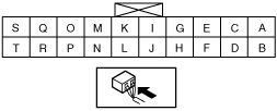
3. By inserting the positive (+) lead of the tester into each climate control unit terminal, measure the voltage according to the terminal voltage table.
Terminal Voltage Table (Reference)
e5u740zw5103
|
|
Terminal |
Signal name |
Connected to |
Measurement condition |
Voltage (V) |
Inspection item (s) |
|---|---|---|---|---|---|
|
A
|
IG2
|
A/C 7.5 A fuse
|
IG SW ON
|
B+
|
• Wiring harness: continuity, short circuit (Climate control unit— fuse: A—A/C 7.5 A)
• A/C 7.5 A fuse
|
|
IG SW LOCK
|
1.0 or less
|
• Wiring harness: continuity, short circuit (Climate control unit— fuse: A—A/C 7.5 A)
|
|||
|
B
|
B+
|
ROOM 15 A fuse
|
Under any condition
|
B+
|
• Wiring harness: continuity, short circuit (Climate control unit— fuse: B—ROOM 15 A)
• ROOM 15 A fuse
|
|
C
|
Blower fan speed control
|
Power MOS FET
|
Fan stopped
|
1.0 or less
|
• Wiring harness: continuity, short circuit (Climate control unit—power MOS FET: C—C)
• Power MOS FET
|
|
Fan: manual 1 (LO) —24
|
2.7—3.4
|
||||
|
Fan: manual 25 (HI)
|
9.6
|
||||
|
D
|
TNS signal
|
TNS relay
|
Headlight switch OFF
|
1.0 or less
|
• Wiring harness: short circuit (Climate control unit—TNS relay: D—D)
• TNS relay
• Headlight switch
|
|
Headlight switch ON
|
B+
|
• Wiring harness: continuity, short circuit (Climate control unit—TNS relay: D—D)
• TNS relay
• Headlight switch
|
|||
|
E
|
Blower motor feedback
|
Power MOS FET
|
Fan stopped
|
B+
|
1. Wiring harness: continuity, short circuit (Climate control unit—power MOS FET: E—B)
2. Power MOS FET
3. Blower motor
4. Blower relay
5. HEATER 40 A fuse
6. Power MOS FET replacement
|
|
Fan: manual LO
|
8.17
|
||||
|
Fan: manual HI
|
0.6
|
||||
|
F
|
Panel control signal
|
Instrument cluster
|
Headlight switch OFF
|
0
|
• Wiring harness: continuity (Climate control unit—instrument cluster: F—1F)
• Instrument cluster
• Climate control unit: terminal voltage (D)
|
|
Headlight switch ON
|
2.7
|
• Wiring harness: short circuit (Climate control unit—instrument cluster: F—1F)
|
|||
|
G
|
Actuator power
|
• Air intake actuator
• Air mix actuator
• Airflow mode actuator
|
IG SW ON
|
B+
|
• Wiring harness: continuity,short circuit (Climate control unit— air intake actuator, air mix actuator, air flow mode actuator: G—A, A, A)
• Air intake actuator
• Air mix actuator
• Airflow mode actuator
|
|
IG SW LOCK
|
1.0 or less
|
||||
|
H
|
GND
|
Body ground
|
Under any condition
|
1.0 or less
|
• Wiring harness: continuity (Climate control unit—GND: H—GND)
|
|
I
|
Plus Signal
|
—
|
—
|
—
|
—
|
|
J
|
—
|
—
|
—
|
—
|
—
|
|
K
|
A/C
|
Refrigerant pressure switch
|
A/C switch ON, fan switch at 1st
|
1.0 or less
|
• Wiring harness: short circuit (Climate control unit—refrigerant pressure switch: K—A)
|
|
A/C switch OFF
|
B+
|
• Wiring harness: continuity, short circuit (Climate control unit—refrigerant pressure switch: K—A) (Refrigerant pressure switch—PCM: C—1J )
• Refrigerant pressure switch
• PCM: terminal voltage (1J)
|
|||
|
L
|
Vehicle speed
|
—
|
—
|
—
|
—
|
|
M
|
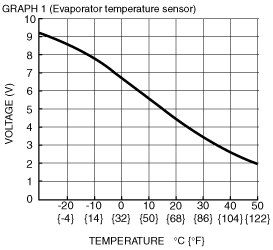
Evaporator temperature sensor input
|
Evaporator temperature sensor
|
Compared with temperature detected by evaporator temperature sensor
|
Refer to graph 1
|
• Wiring harness: continuity (Climate control unit—evaporator temperature sensor: M—B, S—A)
• Wiring harness: short circuit (Climate control unit—evaporator temperature sensor: M—B)
• Evaporator temperature sensor
|
|
N
|
Rear window defroster operation
|
Rear window defroster relay
|
Rear window defroster switch OFF
|
B+
|
• Wiring harness: continuity, short circuit (Climate control unit—rear window defroster relay: N—E)
• Rear window defroster relay
|
|
Rear window defroster switch ON
|
1.0 or less
|
||||
|
O
|
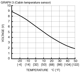
Cabin temperature sensor input
|
Cabin temperature sensor
|
Compared with temperature detected by cabin temperature sensor
|
Refer to graph 3
|
• Wiring harness: continuity (Climate control unit—cabin temperature sensor: O—B, S—A)
• Wiring harness: short circuit (Climate control unit—cabin temperature sensor: O—B)
• Cabin temperature sensor
|
|
Q
|
Solar radiation sensor input
|
Solar radiation sensor
|
Incandescent light (60W) shining on solar radiation sensor from distance of approx. 100mm {3.9 in}
|
4.7
|
• Inspect for continuity or short circuit (Climate control unit—solar radiation sensor: Q—B, S—A)
• Wiring harness: short circuit (Climate control unit—cabin temperature sensor: Q—B)
• Inspect solar radiation sensor
|
|
Light to solar radiation sensor block
|
Below 1.0
|
||||
|
R
|
Water temperature sensor input
|
—
|
—
|
—
|
—
|
|
S
|
Sensor GND
|
• Ambient temperature sensor
• Cabin temperature sensor
• Evaporator temperature sensor
• Solar radiation sensor
|
Under any condition
|
1.0 or less
|
• Wiring harness: continuity (Climate control unit—GND: S—GND)
|
|
T
|
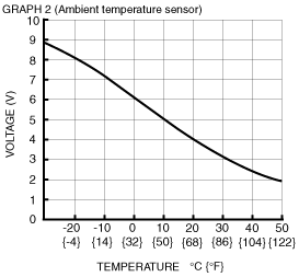
Ambient temperature sensor input
|
Ambient temperature sensor
|
Compared with temperature detected by ambient temperature sensor
|
Refer to graph 2
|
• Wiring harness: continuity (Climate control unit—ambient temperature sensor: T—B, S—A)
• Wiring harness: short circuit (Climate control unit—ambient temperature sensor: T—B)
• Ambient temperature sensor
|
 |
 |
 |
—
|