FOREWORD [IMMOBILIZER SYSTEM (ADVANCED KEYLESS SYSTEM)]
id0902e3960100
-
Note
-
• When the immobilizer system is defective, the engine cannot be started.
-
• If engine condition is normal but security light stays on, inspect for short circuit between security light. Repair or replace the wiring harness if necessary.
-
• The vehicle may fail to start or a DTC may be stored in the PCM if the following occurs:
-
- If a large, metal object is close to a valid key
-
- If an electrical device is close to a valid key
-
- If two or more valid keys are on the same key ring
-
• If any malfunction cannot be identified, verify that no metal object or electrical device is on the key ring.
-
• The security light repeatedly displays a DTC 10 times when the ignition switch is in the ON position.
1. Turn the ignition switch to the ON position.
-
• If there is any malfunction, the security light flashes rapidly for approx. 1 minute and starts displaying a DTC.
-
• If there is no malfunction, the security light illuminates for approx. 3 seconds and goes off.
2. Verify the security light condition and read the DTC according to security light flashing pattern.
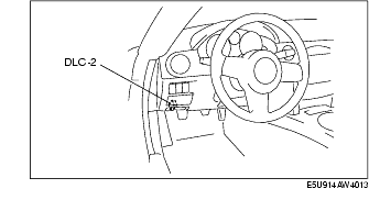
3. Connect the M-MDS to the DLC-2 connector.
4. After the vehicle is identified, select the following items from the initial screen of the M-MDS.
-
• When using the IDS (laptop PC)
-
- Select the "Toolbox" tab.
-
- Select "Self Test".
-
- Select "Modules".
-
- Select "RKE".
-
• When using the PDS (Pocket PC)
-
- Select "Module Tests".
-
- Select the "Optional" tab.
-
- Select "RKE".
-
- Select "Self Test".
5. Verify the DTC according to the directions on the screen.
-
• If any DTCs are displayed, perform troubleshooting according to the corresponding DTC inspection.
6. After completion of repairs, clear all DTCs stored in the keyless control module.
PID/Data Monitor and Record Procedure
1. Connect the M-MDS to the DLC-2 connector.
2. After the vehicle is identified, select the following items from the initial screen of the M-MDS.
-
• When using the IDS (laptop PC)
-
- Select the "Toolbox" tab.
-
- Select "DataLogger".
-
- Select "Modules".
-
- Select "RKE".
-
• When using the PDS (Pocket PC)
-
- Select "Module Tests".
-
- Select the "Optional" tab.
-
- Select "RKE".
-
- Select "DataLogger".
3. Select the applicable PID from the PID table.
4. Verify the PID data according to the directions on the screen.
-
• The PID data screen function is used for monitoring the calculated value. Therefore, if the monitored value of the output parts is not within the specification, inspection of the monitored value of input parts corresponding to applicable output part control is necessary. In addition, because the system does not display output part malfunction as abnormality in the monitored value, it is necessary to inspect the output part individually.