PROCEDURES FOR DETERMINING THE LOCATION OF A MALFUNCTION
id0902e6830500
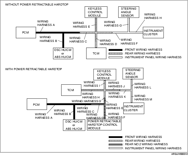
System Wiring Diagram
PCM
1. Inspect the display of DTC U0101, U0121 and/or U0155, using the M-MDS. (See DTC TABLE [MULTIPLEX COMMUNICATION SYSTEM].)
2. Referring to the following table, determine the malfunctioning part of the CAN system.
Without power retractable hardtop
×: Normal
-: Communication error
|
Module
|
Communication status
|
Malfunction location
|
|
DSC HU/CM
ABS HU/CM
|
TCM
|
Keyless control module
|
Instrument cluster
|
|
PCM
|
-
|
-
|
-
|
-
|
• Wiring harness A
• PCM
|
|
-
|
×
|
×
|
×
|
• Wiring harness B
• DSC HU/CM or ABS HU/CM
|
|
×
|
-
|
×
|
×
|
• Wiring harness D
• TCM
|
|
×
|
×
|
-
|
-
|
• Wiring harness E
• Wiring harness F
• Wiring harness H
|
|
×
|
×
|
-
|
×
|
• Wiring harness E
• Keyless control module
|
|
×
|
×
|
×
|
-
|
• Wiring harness F
• Wiring harness H
• Instrument cluster
|
With power retractable hardtop
×: Normal
-: Communication error
|
Module
|
Communication status
|
Malfunction location
|
|
DSC HU/CM
ABS HU/CM
|
TCM
|
Keyless control module
|
Instrument cluster
|
|
PCM
|
-
|
-
|
-
|
-
|
• Wiring harness A
• PCM
|
|
-
|
×
|
×
|
×
|
• Wiring harness B
• DSC HU/CM or ABS HU/CM
|
|
×
|
-
|
×
|
×
|
• Wiring harness H
• TCM
|
|
×
|
×
|
-
|
-
|
• Wiring harness I
• Wiring harness J
• Wiring harness K
• Wiring harness M
|
|
×
|
×
|
-
|
×
|
• Wiring harness I
• Keyless control module
|
|
×
|
×
|
×
|
-
|
• Wiring harness J
• Wiring harness K
• Wiring harness M
• Instrument cluster
|
TCM
1. Inspect the display of DTC U0100 using the M-MDS. (See DTC TABLE [MULTIPLEX COMMUNICATION SYSTEM].)
2. Referring to the following table, determine the malfunctioning part of the CAN system.
Without power retractable hardtop
×: Normal
-: Communication error
|
Module
|
Communication status
|
Malfunction location
|
|
PCM
|
DSC HU/CM
ABS HU/CM
|
Instrument cluster
|
|
TCM
|
-
|
-
|
-
|
• Wiring harness D
• TCM
|
|
-
|
×
|
×
|
• Wiring harness A
• PCM
|
|
×
|
-
|
×
|
• Wiring harness B
• DSC HU/CM or ABS HU/CM
|
|
×
|
×
|
-
|
• Wiring harness F
• Wiring harness H
• Instrument cluster
|
With power retractable hardtop
×: Normal
-: Communication error
|
Module
|
Communication status
|
Malfunction location
|
|
PCM
|
DSC HU/CM
ABS HU/CM
|
Instrument cluster
|
|
TCM
|
-
|
-
|
-
|
• Wiring harness H
• TCM
|
|
-
|
×
|
×
|
• Wiring harness A
• PCM
|
|
×
|
-
|
×
|
• Wiring harness B
• DSC HU/CM or ABS HU/CM
|
|
×
|
×
|
-
|
• Wiring harness J
• Wiring harness K
• Wiring harness M
• Instrument cluster
|
DSC HU/CM or ABS HU/CM
1. Inspect the display of DTC U0100 (DSC), U0101 (DSC), U0155 (DSC), U1900 and/or U2023, using the M-MDS. (See DTC TABLE [MULTIPLEX COMMUNICATION SYSTEM].)
2. Referring to the following table, determine the malfunctioning part of the CAN system.
Without power retractable hardtop
×: Normal
-: Communication error
|
Module
|
Communication status
|
Malfunction location
|
|
PCM
|
TCM
|
Instrument cluster
|
|
DSC HU/CM or ABS HU/CM
|
-
|
-
|
-
|
• Wiring harness B
• DSC HU/CM or ABS HU/CM
|
|
-
|
×
|
×
|
• Wiring harness A
• PCM
|
|
×
|
-
|
×
|
• Wiring harness D
• TCM
|
|
×
|
×
|
-
|
• Wiring harness F
• Wiring harness H
• Instrument cluster
|
With power retractable hardtop
×: Normal
-: Communication error
|
Module
|
Communication status
|
Malfunction location
|
|
PCM
|
TCM
|
Instrument cluster
|
|
DSC HU/CM or ABS HU/CM
|
-
|
-
|
-
|
• Wiring harness B
• DSC HU/CM or ABS HU/CM
|
|
-
|
×
|
×
|
• Wiring harness A
• PCM
|
|
×
|
-
|
×
|
• Wiring harness H
• TCM
|
|
×
|
×
|
-
|
• Wiring harness J
• Wiring harness K
• Wiring harness M
• Instrument cluster
|
Power Retractable Hardtop Control Module
1. Inspect the display of DTC U0100, U0101 and/or U2197, using the M-MDS.
(See DTC TABLE [MULTIPLEX COMMUNICATION SYSTEM].)
2. Referring to the following table, determine the malfunctioning part of the CAN system.
×: Normal
-: Communication error
|
Module
|
Communication status
|
Malfunction location
|
|
PCM
|
TCM
|
Keyless control module
|
Instrument cluster
|
|
Power retractable hardtop control module
|
-
|
-
|
-
|
-
|
• Wiring harness F
• Power retractable hardtop control module
|
|
-
|
×
|
×
|
×
|
• Wiring harness A
• Wiring harness C
• Wiring harness D
• PCM
|
|
×
|
-
|
×
|
×
|
• Wiring harness H
• TCM
|
Keyless Control Module
1. Inspect the display of DTC U0100, U0323 and/or U2023 using the M-MDS.
(See DTC TABLE [MULTIPLEX COMMUNICATION SYSTEM].)
2. Referring to the following table, determine the malfunctioning part of the CAN system.
Without power retractable hardtop
×: Normal
-: Communication error
|
Module
|
Communication status
|
Malfunction location
|
|
PCM
|
Instrument cluster
|
|
Keyless control module
|
-
|
-
|
• Wiring harness E
• Keyless control module
|
|
-
|
×
|
• Wiring harness A
• Wiring harness C
• PCM
|
|
×
|
-
|
• Wiring harness F
• Wiring harness H
• Instrument cluster
|
With power retractable hardtop
×: Normal
-: Communication error
|
Module
|
Communication status
|
Malfunction location
|
|
PCM
|
Instrument cluster
|
Power retractable hardtop control module
|
|
DSC HU/CM or ABS HU/CM
|
-
|
-
|
-
|
• Wiring harness I
• Keyless control module
|
|
-
|
×
|
×
|
• Wiring harness A
• Wiring harness C
• Wiring harness D
• PCM
|
|
×
|
-
|
×
|
• Wiring harness J
• Wiring harness K
• Wiring harness M
• Instrument cluster
|
|
×
|
×
|
-
|
• Wiring harness F
• Power retractable hardtop control module
|
Steering Angle Sensor
1. Inspect the display of DTC U1900 using the M-MDS. (See DTC TABLE [MULTIPLEX COMMUNICATION SYSTEM].)
2. Referring to the following table, determine the malfunctioning part of the CAN system.
Without power retractable hardtop
×: Normal
-: Communication error
|
Module
|
Communication status
|
Malfunction location
|
|
DSC HU/CM
|
|
Steering Angle Sensor
|
-
|
• Wiring harness B
• Wiring harness C
• Wiring harness F
• Wiring harness G
• DSC HU/CM
• Steering Angle Sensor
|
With power retractable hardtop
×: Normal
-: Communication error
|
Module
|
Communication status
|
Malfunction location
|
|
DSC HU/CM
|
|
Steering Angle Sensor
|
-
|
• Wiring harness B
• Wiring harness C
• Wiring harness D
• Wiring harness E
• Wiring harness G
• Wiring harness J
• Wiring harness K
• Wiring harness L
• DSC HU/CM
• Steering Angle Sensor
|
Instrument Cluster
1. Inspect the display of DTC U0100, U0101, U0121, and/or U0214, using the M-MDS. (See DTC TABLE [MULTIPLEX COMMUNICATION SYSTEM].)
2. Referring to the following table, determine the malfunctioning part of the CAN system.
Without power retractable hardtop
×: Normal
-: Communication error
|
Module
|
Communication status
|
Malfunction location
|
|
PCM
|
DSC HU/CM
ABS HU/CM
|
TCM
|
Keyless control module
|
|
Instrument cluster
|
-
|
-
|
-
|
-
|
• Wiring harness F
• Wiring harness H
• Instrument cluster
|
|
-
|
-
|
-
|
×
|
• Wiring harness A
• Wiring harness B
• Wiring harness C
• Wiring harness D
|
|
-
|
×
|
×
|
×
|
• Wiring harness A
• PCM
|
|
×
|
-
|
×
|
×
|
• Wiring harness B
• DSC HU/CM or ABS HU/CM
|
|
×
|
×
|
-
|
×
|
• Wiring harness D
• TCM
|
|
×
|
×
|
×
|
-
|
• Wiring harness E
• Keyless control module
|
With power retractable hardtop
×: Normal
-: Communication error
|
Module
|
Communication status
|
Malfunction location
|
|
PCM
|
DSC HU/CM
ABS HU/CM
|
TCM
|
Keyless control module
|
|
Instrument cluster
|
-
|
-
|
-
|
-
|
• Wiring harness M
• Instrument cluster
|
|
-
|
-
|
-
|
×
|
• Wiring harness A
• Wiring harness B
• Wiring harness C
• Wiring harness D
• Wiring harness E
• Wiring harness G
• Wiring harness H
|
|
-
|
×
|
×
|
×
|
• Wiring harness A
• PCM
|
|
×
|
-
|
×
|
×
|
• Wiring harness B
• DSC HU/CM or ABS HU/CM
|
|
×
|
×
|
-
|
×
|
• Wiring harness H
• TCM
|
|
×
|
×
|
×
|
-
|
• Wiring harness I
• Keyless control module
|
Repair Procedure
1. Inspect the connector of malfunctioning module.
-
• If there is any malfunction, repair or replace the connector.
2. Inspect the malfunctioning wiring harnesses as follow:
-
• If there is any malfunction, repair or replace the wiring harnesses.
-
• If there is no malfunction, replace the malfunctioning module.
-
- Short to GND
-
- Short to power supply
-
- Twisted pair short each other
-
- Open circuit
3. Make sure to reconnect all disconnected connectors.
4. Clear the CAN system related DTCs using the M-MDS.
5. Verify if the CAN system related DTCs are displayed using the M-MDS.
-
• If the same following DTCs are present, replace the malfunctioning module.
-
- U0073 (PCM, TCM, DSC HU/CM, ABS HU/CM, keyless control module, instrument cluster, power retractable hardtop control module)
-
- U2516 (steering angle sensor)
-
• If other DTC is present, perform the appropriate DTC inspection. (See DTC TABLE [MULTIPLEX COMMUNICATION SYSTEM].)