|
1
|
• Attempt to lock/unlock the door with the transmitter (card key).
• Does the operation indicator light (LED) illuminate?
|
Yes
|
Go to the next step.
|
|
No
|
Go to Step 10.
|
|
2
|
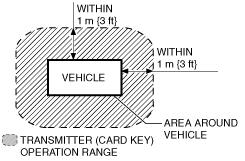
• Did the customer activate the transmitter (card key) within operative area (Within 1 m {3 ft}from area around vehicle)?
|
Yes
|
Go to the next step.
|
 |
No
|
The system is normal.
Explain to the customer that the system does not work without the system operative area.
|
|
3
|
• Did the customer use the keyless entry system in particular area, such as being near TV towers, power plants, power lines, or factories?
|
Yes
|
The system is normal.
Area of operation is subject.
Explain effect of outside interference on the transmitter (card key) to the customer.
|
|
No
|
Go to the next step.
|
|
4
|
• Did the customer activate the keyless entry system with all following conditions satisfied?
-
― All doors closed
― Mechanical key is not in steering lock unit.
― Start knob is at LOCK position.
― Start knob is not pressed.
|
Yes
|
Go to the next step.
|
|
No
|
The system is normal.
Explain to the customer that the system does not work without these conditions satisfied.
|
|
5
|
• Are any of the following after-market electrical parts on the vehicle?
-
― Cellular phone
― Radio-wave equipment
― Remote engine starter
― TV
― Other
|
Yes
|
Go to the next step.
|
|
No
|
Go to Step 7.
|
|
6
|
• Disconnect the after-market electrical parts connectors and attempt to lock/unlock the doors with the transmitter (card key).
• Does the keyless entry system work?
|
Yes
|
The system is normal. The after-market electrical parts are interfering with the keyless entry system.
|
|
No
|
Go to the next step.
|
|
7
|
• Is there repair record of the customer's keyless entry system?
|
Yes
|
Go to the next step.
|
|
No
|
Go to Step 10.
|
|
8
|
• Does the malfunction occur after the repair?
|
Yes
|
Go to the next step.
|
|
No
|
Go to Step 10.
|
|
9
|
• Is the malfunction corrected when the ID numbers for all the customer's transmitters (card key) are updated?
|
Yes
|
System is normal. (Explain to the customer that the malfunction occurred because all the transmitter (card key) ID numbers were not updated even though the body control module or a transmitter (card key) was replaced in the previous servicing.)
|
|
No
|
Go to the next step.
|
|
10
|
• Visually inspect the transmitter (card key) battery for the following:
-
― Battery direction (polarity)
― Battery type (CR2025)
― Corrosion, soiling, deformation of battery terminals (plus/minus terminals).
― Contact malfunction between the battery terminal and battery when battery is inserted
• Is there any malfunction?
|
Yes
|
Battery insertion direction, battery type problem:
• Properly install the battery or replace the battery with a specified one (CR2025), then go to the next step.
Battery terminal malfunction:
• Clean corrosion and soiling or repair the terminal, then go to the next step.
|
|
No
|
Go to Step 12.
|
|
11
|
• Does the keyless entry system operate properly?
|
Yes
|
Troubleshooting completed.
|
|
No
|
Go to the next step.
|
|
12
|
-
Note
-
• Use a new monitor battery (normal battery) or one from another vehicle which operates normally.
• Replace the battery in all the transmitters (card key) with a monitor-use battery (normal battery).
• For each transmitter (card key), verify that the transmitter (card key) operation indicator light (LED) illuminates when a button is operated.
• Does operation indicator light (LED) for each transmitter (card key) operate?
|
Yes
|
Go to the next step.
|
|
No
|
If the operation indicator light (LED) does not illuminate, replace the transmitter (card key), then go to Step 24.
|
|
13
|
-
Note
-
• Inspect for all transmitters (card key).
• Inspect while the batteries for all of the transmitters (card key) are replaced with monitor-use batteries (normal battery).
• Verify the operation of keyless entry system using all of the transmitters (card key).
• Does the keyless entry system operate normally?
|
Yes
|
Replace the battery, then go to Step 24.
|
|
No
|
Go to the next step.
|
|
14
|
• Inspect for the keyless receiver installation.
• Is the bracket securely installed on the keyless receiver?
|
Yes
|
Go to the next step.
|
|
No
|
Install the bracket securely, and then go to the next step.
|
|
15
|
• Turn the ignition switch to the LOCK position.
• Measure the voltage at keyless receiver terminal A?
• Is the voltage B+?
|
Yes
|
Go to the next step.
|
|
No
|
• Inspect ROOM 15 A fuse.
• Inspect and repair the wiring harness between the fuse block and the keyless receiver as necessary.
|
|
16
|
• Measure the voltage at keyless receiver terminal E?
• Is the voltage 0 V?
|
Yes
|
Go to the next step.
|
|
No
|
• Inspect and repair the wiring harness between the ground wire and the keyless receiver as necessary.
• Re-tighten the ground wire as necessary.
|
|
17
|
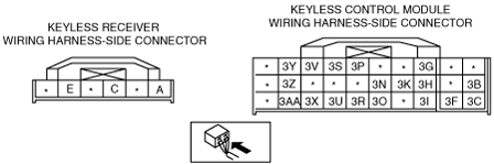
• Disconnect the keyless receiver connector (6-pin) and keyless control module connector (27-pin).
• Is there continuity between the following terminals?
-
― Keyless receiver connector terminal A—keyless control module connector terminal 3S
― Keyless receiver connector terminal C—keyless control module connector terminal 3U
― Keyless receiver connector terminal E—GND
|
Yes
|
Go to the next step.
|
|
No
|
• Inspect and repair the wiring harness between the keyless control module and the keyless receiver, then go to the next step.
|
|
18
|
• Measure the signal wave pattern of keyless control module terminal 3U using an oscilloscope while the transmitter (card key) is operated with the auxiliary key removed from the ignition key cylinder.
• Does the wave pattern change when the transmitter (card key) is operated?
-
Note
-
• Perform the oscilloscope setting using 0.5 V/DIV (Y), 100 ms/DIV (X), DC range.
|
Yes
|
Go to the next step.
|
|
No
|
Replace the keyless receiver, and then go to the next step.
|
|
19
|
• Measure the voltage at the keyless control module terminals 3B, 3I, 1E and 1F.
-
― Terminal 3B: IG1 voltage
― Terminal 1E, 1F: B+
― Terminal 3I: ACC voltage
• Is the voltage as above?
|
Yes
|
Go to the next step.
|
|
No
|
• Inspect for fuse.
• Inspect and repair the wiring harness between the keyless control module and the fuse block as necessary.
• Then go to the next step.
|
|
20
|
• Measure the voltage at keyless control module terminal 3C?
• Is the voltage 0 V?
|
Yes
|
Go to the next step.
|
|
No
|
• Inspect and repair the wiring harness between the ground wire and the keyless control module as necessary.
• Re-tighten the ground wire as necessary.
• Then go to the next step.
|
|
21
|
• Turn the start knob to LOCK position with mechanical key is not ignition switch, and the start knob is not pushed.
• Measure the voltage following keyless control module connector.
-
― Terminal 3O (keyless switch): below 1.0 V
― Terminal 3N (start knob (push switch)): below 1.0 V
― Terminal 3I (ACC voltage): below 1.0 V
― Terminal 3B (IG1 voltage): below 1.0 V
• Is the signal voltage normal?
|
Yes
|
Go to the next step.
|
|
No
|
• Inspect for key reminder switch.
• Inspect and repair the wiring harness between the steering lock unit (key reminder switch) and the keyless control module.
• Then go to the next step.
|
|
22
|
• Monitor the following PIDs for the keyless control module using the M-MDS:
-
― DRSW_D (Door switch (driver's door))
― DRSW_P (Door switch (passenger's door))
― TR/LG_SW (Trunk compartment light switch)
• Does each monitor value agree with the door open/close condition?
|
Yes
|
Go to the next step.
|
|
No
|
Inspect the door switch.
If normal, inspect for open or short at the door switch related harness.
|
|
23
|
• Measure the voltage at the keyless control module terminals 1C and 1A while operating the transmitter (card key).
-
― All doors locked: 1.0 V or less→B+→1.0 V or less (terminal C)
― Any door unlocked: 1.0 V or less→B+→1.0 V or less (terminal 1A)
• Is the voltage as above?
|
Yes
|
Replace the keyless control module.
|
|
No
|
Inspect and repair the wiring harness between the keyless control module and door lock actuator.
If the wiring harness is normal, inspect the door lock actuator.
|
|
24
|
• Does the keyless entry system operate properly?
|
Yes
|
Troubleshooting completed. Explain repairs to the customers.
|
|
No
|
Re-inspect the malfunction symptoms, then repeat form Step 1 if malfunction recurs.
|