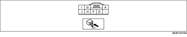
1. Remove the flasher unit with the connector still connected.
2. Measure the voltage at each terminal (other than terminal F).
3. Disconnect the flasher unit connector.
4. Verify that continuity at terminal F is as indicated in the Terminal Voltage Table (Reference).
|
Terminal
|
Signal name
|
Connected to
|
Measured condition
|
Voltage (V)/Continuity
|
Inspection item(s)
|
|
|---|---|---|---|---|---|---|
|
A
|
Power supply
|
HAZARD 10 A fuse
|
Under any condition
|
B+
|
• HAZARD 10 A fuse
• Related wiring harnesses
|
|
|
D
|
Flasher unit output
|
Turn light (LH)
|
Turn light switch (LH) is on.
|
Turn light (LH) flashes.
|
Alternates between 1.0 or less and B+
|
• Turn light (LH)
• Related wiring harnesses
|
|
Hazard warning switch is on.
|
||||||
|
Except above
|
1.0 or less
|
|||||
|
F
|
GND
|
Body ground
|
Under any condition: Inspect for continuity to ground.
|
Continuity detected
|
• GND
|
|
|
G
|
Flasher unit output
|
Turn light (RH)
|
Turn light switch (RH) is on.
|
Turn light (RH) flashes.
|
Alternates between 1.0 or less and B+
|
• Turn light (RH)
• Related wiring harnesses
|
|
Hazard warning switch is on.
|
||||||
|
Except above
|
1.0 or less
|
|||||
|
H
|
Hazard warning switch input
|
Hazard warning switch
|
Hazard warning switch is on.
|
1.0 or less
|
• Hazard warning switch
• Related wiring harnesses
|
|
|
Hazard warning switch is off.
|
B+
|
|||||
|
I
|
Turn switch (RH) input
|
Turn switch
|
Turn the ignition switch to the ON position.
|
Turn switch (RH) is on.
|
B+
|
• Turn switch
(SeeLIGHT SWITCH INSPECTION.)
• Related wiring harnesses
|
|
Except above
|
1.0 or less
|
|||||
|
J
|
Turn switch (LH) input
|
Turn switch
|
Turn the ignition switch to the ON position.
|
Turn switch (LH) is on.
|
B+
|
• Turn switch
(SeeLIGHT SWITCH INSPECTION.)
• Related wiring harnesses
|
|
Except above
|
1.0 or less
|
|||||