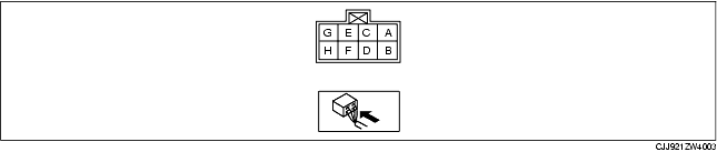
|
Terminal
|
Signal name
|
Connected to
|
Measured condition
|
Voltage (V)/Continuity
|
Inspection item(s)
|
|
A
|
Push switch signal
|
Keyless control module
|
Start knob pressed
|
B+
|
• Keyless control module
• Related wiring harnesses
|
|
Start knob released
|
1.0 or less
|
|
B
|
Power supply
|
Fuse
|
Under any condition
|
B+
|
• Fuse
• Related wiring harnesses
|
|
C
|
Key reminder switch signal
|
Keyless control module
|
Key inserted
|
B+
|
• Keyless control module
• Related wiring harnesses
|
|
Key removed
|
1.0 or less
|
|
D
|
Power supply
|
Fuse
|
Under any condition
|
B+
|
• Fuse
• Related wiring harnesses
|
|
E
|
Power supply
|
Fuse
|
Under any condition
|
B+
|
• Fuse
• Related wiring harnesses
|
|
F
|
Ignition key illumination signal
|
Ignition key illumination bulb
|
Ignition switch off and driver-side door opened.
|
1.0 or less
|
• Ignition key illumination bulb
• Related wiring harnesses
|
|
30 s or more after driver-side door closed.
|
B+
|
|
G
|
Serial communication
|
Keyless control module
|
Under any condition: Inspect for continuity to keyless control module.
|
Continuity detected
|
Related wiring harnesses
|
|
H
|
GND
|
Body ground
|
Under any condition: Inspect for continuity to GND.
|
Continuity detected
|
Related wiring harnesses
|