 |
amxzzn00000675
INPUT/OUTPUT CHECK MODE OPERATION
id092200100900
Operation procedure
Input circuit check
|
Check code |
Parts sending input signal |
|---|---|
|
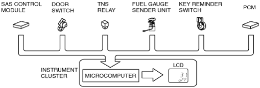
01
|
Buckle switch (driver’s side)
|
|
04
|
Door switch
|
|
08
|
TNS relay
|
|
22
|
Fuel gauge sender unit
|
|
31
|
Key reminder switch (built into the ignition switch or steering lock unit)
|
|
58
|
Buckle switch (passenger’s side)
|
|
59
|
Fuel system signal
|
amxzzn00000675
|
Individual circuit check
|
Check code |
Parts sending input signal |
|---|---|
|
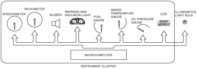
12
|
Speedometer
|
|
13
|
Tachometer
|
|
14
|
Buzzer
|
|
16
|
Fuel-level warning light
|
|
18
|
Ignition key illumination output
|
|
23
|
Fuel gauge
|
|
25
|
Water temperature gauge
|
|
26
|
LCD, warning and indicator light
|
|
28
|
Oil pressure gauge
|
|
57
|
Panel light control
|
amxzzn00000676
|
PID/Data Monitor and Record
Monitor item table
|
Monitor item |
Input-output signal/part name |
Unit/State |
Terminal |
|
|---|---|---|---|---|
|
IC_DTC_CNT
|
Number of continuous DTCs
|
—
|
—
|
|
|
IC_ECT
|
Water temperature gauge
|
°F
|
°C
|
1J, 1L
|
|
IC_NUMKEYS
|
Number of key ID numbers registered with the vehicle
|
—
|
—
|
|
|
IC_ODO_CNT
|
Odometer
|
m
|
1J, 1L
|
|
|
IC_SPDMTR
|
Speedometer
|
MPH
|
KPH
|
|
|
IC_TACHO
|
Tachometer
|
RPM
|
||
|
IC_VPWR
|
Power supply voltage
|
V
|
1C
|
|