 |
h5e511bm002
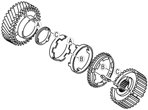
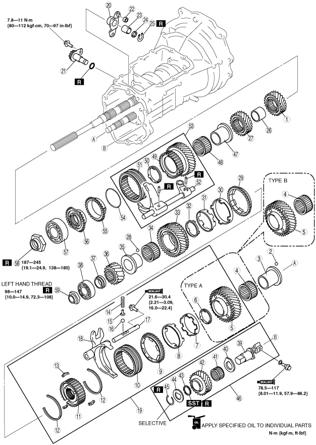
REVERSE GEAR COMPONENT AND 3RD/4TH GEAR COMPONENT ASSEMBLY
d5e051117040m03
1. Assemble in the order indicated in the table.
h5e511bm002
|
|
1
|
3rd gear
|
|
2
|
Steel ball
|
|
3
|
Needle bearing inner race
|
|
4
|
Needle bearing
(See Needle Bearing Assembly Note.)
|
|
5
|
3rd counter gear
|
|
6
|
Friction damper
|
|
7
|
Inner cone
|
|
8
|
Double cone
|
|
9
|
Synchronizer ring
|
|
10
|
Clutch hub sleeve
|
|
11
|
3rd/4th clutch hub
|
|
12
|
Synchronizer key spring
|
|
13
|
Synchronizer key
|
|
14
|
Detent spring
|
|
15
|
Spring seat
|
|
16
|
Detent ball
|
|
17
|
3rd/4th shift rod
|
|
18
|
3rd/4th shift fork
|
|
19
|
3rd/4th clutch hub component
|
|
20
|
Counter lever
|
|
21
|
Counter lever shaft component
|
|
22
|
Bush
|
|
23
|
Needle bearing
|
|
24
|
Spacer
|
|
25
|
Retaining ring
|
|
26
|
Spacer
|
|
27
|
4th gear
|
|
28
|
Steel ball
|
|
29
|
Synchronizer ring
|
|
30
|
Double cone
|
|
31
|
Inner cone
|
|
32
|
Friction damper
|
|
33
|
4th counter gear
|
|
34
|
Needle bearing
|
|
35
|
Needle bearing race
|
|
36
|
Reverse counter gear
|
|
37
|
Collar
|
|
38
|
Countershaft rear bearing
|
|
39
|
Reverse idler gear shaft
|
|
40
|
Thrust washer
|
|
41
|
Needle bearing
|
|
42
|
Reverse idler gear
|
|
43
|
Friction damper
|
|
44
|
Thrust washer
|
|
45
|
Retaining ring
|
|
46
|
Reverse idler gear component
|
|
47
|
Needle bearing race
|
|
48
|
Needle bearing
|
|
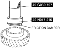
49
|
Reverse gear
|
|
50
|
Friction damper
|
|
51
|
Clutch hub sleeve
|
|
52
|
Reverse shift fork
|
|
53
|
Reverse gear, shift fork component
|
|
54
|
Synchronizer key spring
|
|
55
|
Synchronizer ring
|
|
56
|
Reverse synchronizer cone
|
|
57
|
Mainshaft rear bearing
|
|
58
|
Locknut
|
|
59
|
Locknut
|
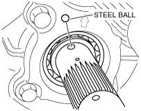
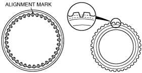
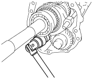
3rd Gear Bearing Inner Race Assembly Note
1. Install the steel ball to the countershaft.
e5u511bm5032
|
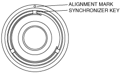
2. Align the ball groove position of the 3rd gear bearing inner race and assemble it to the countershaft.
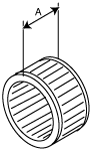
Needle Bearing Assembly Note
h5e511bm003
|
3rd Counter Gear, 3rd/4th Clutch Hub Component and 3rd/4th Shift Fork Assembly Note
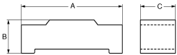
1. Assemble the 3rd drive gear and 3rd/4th clutch hub component.
a6e5110m131
|
|
|
A |
B |
C |
|---|---|---|---|
|
5th/6th
|
17.0 {0.670}
|
4.25 {0.167}
|
5.0 {0.197}
|
e5u511bm5057
|
e5u511bm5058
|
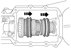
2. Assemble the 3rd counter gear component, 3rd/4th clutch hub component, and 3rd/4th shift fork component as a single unit.
e5u511bm5018
|
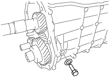
3. Install the 3rd/4th shift rod retaining bolt.
e5u511bm5017
|
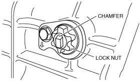
Counter Lever Shaft Assembly Note
Locknut is loosened
1. Assemble the counter lever shaft to the transmission (counter lever).
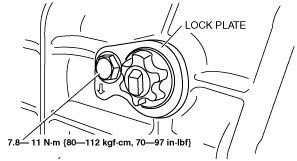
2. Assemble the lock plate to the counter lever shaft.
GHG0517M5009
|
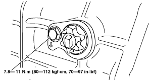
3. Apply sealant (TB2440B) to the thread area of the locknut.
4. Tighten the locknut with the chamfer of the counter lever shaft end facing upright as shown in the figure.
GHG0517M5008
|
5. After assembling the transmission, verify the 3rd/4th shift stroke.
GHG0517M5008
|
Locknut is not loosened
1. Assemble the counter lever shaft component to the transmission.
GHG0517M5007
|
2. After assembling the transmission, verify the 3rd/4th shift stroke.
GHG0517M5008
|
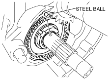
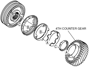
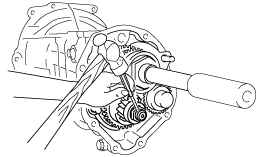
4th Counter Gear, 4th Synchronizer ring, 4th Bearing Inner Race Assembly Note
1. Install the steel ball to the countershaft.
e5u511bm5035
|
2. Assemble the 4th counter gear component to the 3rd/4th clutch hub.
e5u511bm5062
|
3. Align the ball groove position of the 4th counter gear bearing inner race and assemble it to the countershaft.
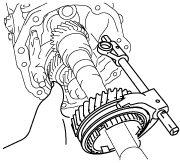
Reverse Idler Gear Component Assembly Note
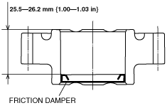
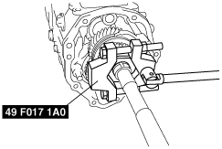
1. Using the SST, install the friction damper to the reverse idler gear.
g5u511bms038
|
e5u511bm5088
|
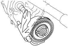
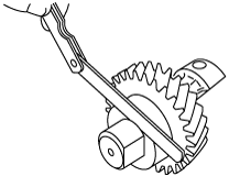
2. Assemble the reverse idler gear component.
3. Measure the clearance between the retaining ring and thrust washer.
e5u511bm5039
|
Reverse idler gear retaining ring
|
Thickness (mm {in}) |
|---|
|
1.5 {0.059}
|
|
1.6 {0.063}
|
|
1.7 {0.067}
|
|
1.8 {0.071}
|
|
1.9{0.075}
|
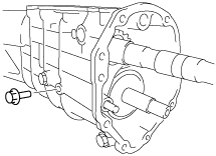
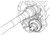
4. Install the reverse idler gear component to the transmission case.
e5u511bm5070
|
5. Install the reverse idler gear shaft retaining bolt.
e5u511bm5015
|
Reverse Gear and Reverse Clutch Hub Component Assembly Note
1. Assemble the reverse gear and clutch hub sleeve.
e5u511bm5061
|
2. Assemble the reverse gear, clutch hub sleeve and shift fork as a single unit.
e5u511bm5040
|
Mainshaft Rear Bearing and Countershaft Rear Bearing Locknut Assembly Note
1. Slide the 5th/6th and 1st/2nd clutch hub sleeves to lock the transmission into 5th and 2nd gears.
e5u511bm5011
|
2. Insert the mainshaft rear bearing into the mainshaft and install the locknut.
3. Attach the SST to the locknut and tighten the nut to the specified torque.
e5u511bm5012
|
4. Tighten the countershaft locknut in the counterclockwise direction.
e5u511bm5013
|
5. Using the pin punch, stake the mainshaft rear bearing locknut.
e5u511bm5042
|
6. Using the pin punch, stake the countershaft rear bearing locknut.
e5u511bm5089
|