DTC P0403 [L8, LF]


id0102b1807100

DTC P0403

EGR valve (stepping motor) circuit problem

DETECTION CONDITION
•  The PCM monitors the EGR valve control signal voltage and current. If the following conditions are met, the PCM determines that there is a EGR control circuit problem.
―  The PCM turns the EGR valve off, but the voltage of the EGR valve control signal remains low.
―  The PCM turns the EGR valve on, but the current of the EGR valve control signal remains high.
Diagnostic support note
•  This is a continuous monitor (CCM).
•  The MIL illuminates if the PCM detects the above malfunction conditions in two consecutive drive cycles or in one drive cycle while the DTC for the same malfunction has been stored in the PCM.
•  PENDING CODE is available if the PCM detects the above malfunction condition during the first drive cycle.
•  FREEZE FRAME DATA (Mode 2/Mode 12) is available.
•  The DTC is stored in the PCM memory.
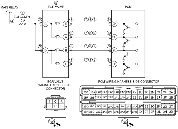
POSSIBLE CAUSE
•  EGR valve connector or terminals malfunction
•  Open circuit or short to ground in wiring harness between the main relay and EGR valve
―  Short to ground in wiring harness between main relay and EGR valve terminal C
―  Short to ground in wiring harness between main relay and EGR valve terminal D
―  EGI COMP1 10 A fuse malfunction
―  Open circuit in wiring harness between main relay and EGR valve terminal C
―  Open circuit in wiring harness between main relay and EGR valve terminal D
•  EGR valve malfunction
•  PCM connector or terminals malfunction
•  Short to ground in wiring harness between the following terminals:
―  EGR valve terminal E and PCM terminal 2K
―  EGR valve terminal A and PCM terminal 2G
―  EGR valve terminal B and PCM terminal 2L
―  EGR valve terminal F and PCM terminal 2H
•  Short to power supply in wiring harness between the following terminals:
―  EGR valve terminal E and PCM terminal 2K
―  EGR valve terminal A and PCM terminal 2G
―  EGR valve terminal B and PCM terminal 2L
―  EGR valve terminal F and PCM terminal 2H
•  Open circuit in wiring harness between the following terminals:
―  EGR valve terminal E and PCM terminal 2K
―  EGR valve terminal A and PCM terminal 2G
―  EGR valve terminal B and PCM terminal 2L
―  EGR valve terminal F and PCM terminal 2H
•  PCM malfunction

Diagnostic procedure

STEP

INSPECTION

ACTION

1
VERIFY FREEZE FRAME DATA (MODE 12) HAS BEEN RECORDED
•  Has the FREEZE FRAME DATA (Mode 12) been recorded?
Yes
Go to the next step.
No
Record the FREEZE FRAME DATA (Mode 12) on repair order, then go to the next step.
2
VERIFY RELATED SERVICE INFORMATION AVAILABILITY
•  Verify related Service Information availability.
•  Is any related Service Information available?
Yes
Perform repair or diagnosis according to the available Service Information.
•  If the vehicle is not repaired, go to the next step.
No
Go to the next step.
3
INSPECT EGR VALVE CONNECTOR AND TERMINALS
•  Turn the ignition switch off.
•  Disconnect the EGR valve connector.
•  Inspect for poor connection (such as damaged/pulled-out pins, and corrosion).
•  Is there any malfunction?
Yes
Repair or replace the connector or terminals, then go to Step 10.
No
Go to the next step.
4
INSPECT EGR VALVE POWER SUPPLY CIRCUIT FOR OPEN CIRCUIT OR SHORT TO GROUND
•  EGR valve connector is disconnected.
•  Turn the ignition switch to the ON position (engine off).
•  Measure the voltage between the following terminals (wiring harness-side) and body ground:
―  EGR valve terminal C
―  EGR valve terminal D
•  Is the voltage B+?
Yes
Go to the next step.
No
Inspect the EGI COMP1 10 A fuse.
If the fuse is melt:
•  Repair or replace the wiring harness for a possible short to ground, then replace the fuse.
If the fuse is deterioration:
•  Replace the fuse.
If the fuse is normal:
•  Repair or replace the wiring harness for a possible open circuit.
Go to Step 10.
5
INSPECT EGR VALVE
•  Turn the ignition switch off.
•  Reconnect the EGR valve connector.
•  Inspect the EGR valve.
•  Is there any malfunction?
Yes
Replace the EGR valve, then go to Step 10.
No
Go to the next step.
6
INSPECT PCM CONNECTOR AND TERMINALS
•  Disconnect the PCM connector.
•  Inspect for poor connection (such as damaged/pulled-out pins, and corrosion).
•  Is there any malfunction?
Yes
Repair or replace the connector or terminals, then go to Step 10.
No
Go to the next step.
7
INSPECT EGR VALVE CIRCUIT FOR SHORT TO GROUND
•  PCM connector is disconnected.
•  Disconnect the EGR valve connector.
•  Inspect for continuity between the following terminals (wiring harness-side) and body ground:
―  EGR valve terminal E
―  EGR valve terminal A
―  EGR valve terminal B
―  EGR valve terminal F
•  Is there continuity?
Yes
Repair or replace the wiring harness for a possible short to ground, then go to Step 10.
No
Go to the next step.
8
INSPECT EGR VALVE CIRCUIT FOR SHORT TO POWER SUPPLY
•  EGR valve and PCM connectors are disconnected.
•  Turn the ignition switch to the ON position (engine off).
•  Measure the voltage between the following terminals (wiring harness-side) and body ground:
―  EGR valve terminal E
―  EGR valve terminal A
―  EGR valve terminal B
―  EGR valve terminal F
•  Is there any voltage?
Yes
Repair or replace the wiring harness for a possible short to power supply, then go to Step 10.
No
Go to the next step.
9
INSPECT EGR VALVE CIRCUIT FOR OPEN CIRCUIT
•  EGR valve and PCM connectors are disconnected.
•  Turn the ignition switch off.
•  Inspect for continuity between the following terminals (wiring harness-side):
―  EGR valve terminal E and PCM terminal 2K
―  EGR valve terminal A and PCM terminal 2G
―  EGR valve terminal B and PCM terminal 2L
―  EGR valve terminal F and PCM terminal 2H
•  Is there continuity?
Yes
Go to the next step.
No
Repair or replace the wiring harness for a possible open circuit, then go to the next step.
10
VERIFY DTC TROUBLESHOOTING COMPLETED
•  Make sure to reconnect all disconnected connectors.
•  Clear the DTC from the PCM memory using the M-MDS.
•  Start the engine and warm it up completely.
•  Perform the KOEO/KOER self test.
•  Is the PENDING CODE for this DTC present?
Yes
Replace the PCM, then go to the next step.
No
Go to the next step.
11
VERIFY AFTER REPAIR PROCEDURE
•  Perform the “AFTER REPAIR PROCEDURE”.
•  Are any DTCs present?
Yes
Go to the applicable DTC troubleshooting.
No
DTC troubleshooting completed.