 |
am6zzw00002589
VARIABLE VALVE TIMING ACTUATOR INSPECTION [LF]
id0110a9801245
1. Remove the battery cover. (See BATTERY REMOVAL/INSTALLATION [L8, LF].)
2. Disconnect the negative battery cable. (See BATTERY REMOVAL/INSTALLATION [L8, LF].)
3. Remove the plug hole plate. (See PLUG HOLE PLATE REMOVAL/INSTALLATION [L8, LF].)
4. Disconnect the ventilation hose. (See QUICK RELEASE CONNECTOR (EMISSION SYSTEM) REMOVAL/INSTALLATION [L8, LF].)
5. Remove the front suspension tower bar (joint). (See FRONT SUSPENSION TOWER BAR REMOVAL/INSTALLATION.)
6. Remove the CMP sensor. (See CAMSHAFT POSITION (CMP) SENSOR REMOVAL/INSTALLATION [L8, LF].)
7. Disconnect the oil control valve (OCV) connector.
8. Disconnect the P/S pressure switch connector.
9. Remove the ignition coils. (See IGNITION COIL REMOVAL/INSTALLATION [L8, LF].)
10. Remove the cylinder head cover. (See TIMING CHAIN REMOVAL/INSTALLATION [L8, LF].)
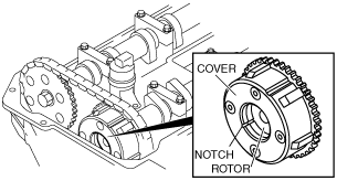
11. Confirm that notch of the rotor and bump of the cover at the variable valve timing actuator are aligned and fitted.
am6zzw00002589
|
12. Install the cylinder head cover. (See TIMING CHAIN REMOVAL/INSTALLATION [L8, LF].)
13. Install the ignition coils. (See IGNITION COIL REMOVAL/INSTALLATION [L8, LF].)
14. Connect the P/S pressure switch connector.
15. Connect the OCV connector.
16. Install the CMP sensor. (See CAMSHAFT POSITION (CMP) SENSOR REMOVAL/INSTALLATION [L8, LF].)
17. Install the front suspension tower bar (joint). (See FRONT SUSPENSION TOWER BAR REMOVAL/INSTALLATION.)
18. Connect the ventilation hose. (See QUICK RELEASE CONNECTOR (EMISSION SYSTEM) REMOVAL/INSTALLATION [L8, LF].)
19. Install the plug hole plate. (See PLUG HOLE PLATE REMOVAL/INSTALLATION [L8, LF].)
20. Connect the negative battery cable. (See BATTERY REMOVAL/INSTALLATION [L8, LF].)
21. Install the battery cover. (See BATTERY REMOVAL/INSTALLATION [L8, LF].)