 |
e5u110zw5899
OIL CONTROL VALVE (OCV) INSPECTION [L8, LF]
id0110a9801400
Coil Resistance Inspection
1. Remove the battery cover. (See BATTERY REMOVAL/INSTALLATION [L8, LF].)
2. Disconnect the negative battery cable. (See BATTERY REMOVAL/INSTALLATION [L8, LF].)
3. Disconnect the OCV connector.
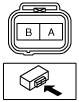
4. Measure the resistance between terminals A and B using an ohmmeter.
e5u110zw5899
|
5. Connect the OCV connector.
Spool Valve Operation Inspection
1. Remove the battery cover. (SeeBATTERY REMOVAL/INSTALLATION [L8, LF].)
2. Disconnect the negative battery cable. (See BATTERY REMOVAL/INSTALLATION [L8, LF].)
3. Remove the OCV. (See OIL CONTROL VALVE (OCV) REMOVAL/INSTALLATION [L8, LF].)
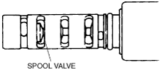
4. Verify that the spool valve in the OCV is in the maximum valve timing retard position as indicated in the figure.
amxzzw00002165
|
5. Verify that the battery is fully charged.
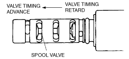
6. Apply battery positive voltage between the OCV terminals and verify that the spool valve operates and moves to the maximum valve timing advance position.
amxzzw00002166
|
7. Stop applying battery positive voltage and verify that the spool valve returns to the maximum valve timing retard position.