amxzzn00000062
|
FUEL INJECTION CONTROL OPERATION [L8, LF]
id0140i7101900
Operation
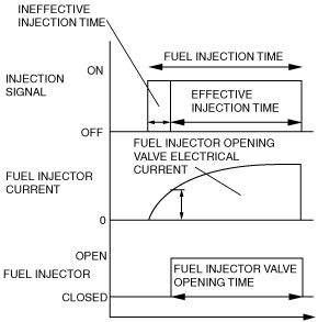
Injection timing
Injection Time
amxzzn00000062
|
Determination of Effective Injection Time
amxzzn00000063
|
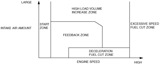
Start zone
Feedback Zone
High load volume increase zone
Excessive speed fuel cut zone
Deceleration fuel cut zone
Calculation method list for fuel injection time
|
Contents
(Fuel injection time, calculation method, or determination method)
|
Control zone
|
||||||
 |
 |
 |
 |
 |
|||
|
Injection time at start
|
Set value according to engine coolant temperature (low engine coolant temperature→long injection time)
|
A
|
|
|
|
|
|
|
Basic injection time
|
Basic injection time = charging efficiency x fuel flow coefficient
|
|
A
|
A
|
|
|
|
|
Fuel cut
|
Fuel injection time = 0
|
|
|
|
A
|
A
|
|
|
Ineffective injection time
|
Set time according to injector performance
|
A
|
A
|
A
|
|
|
|
|
Volume increase correction at engine start
|
Purpose: Maintains stability of engine speed just after engine start
Correction condition
• Specified time according to engine coolant temperature directly after engine start
Correction amount
• Low engine coolant temperature→large correction
• Low intake air temperature→large correction
|
B
|
B
|
|
|
|
|
|
A/F sensor feedback correction
|
Purpose: Controls air/fuel ratio to the theoretical air/fuel ratio
Correction condition
• When engine coolant temperature is at set value or more
Correction amount
• A/F sensor current value 0 mA or less→volume decrease correction
• A/F sensor current value 0 mA or more→volume increase correction
|
|
B
|
|
|
|
|
|
HO2S feedback correction
|
Purpose: Corrects feedback amount according to deterioration of A/F sensor and catalytic converter
Correction condition
• Engine coolant temperature is at set value or more
• Engine speed is 500—4,250 rpm
• Charging efficiency is 10—80%
Correction amount
• According to HO2S electromotive force→correction
|
|
B
|
|
|
|
|
|
D-range correction
(AT)
|
Purpose: Ensures engine speed stability during D-range shifting
Correction condition
• Throttle valve fully-closed and shifted into D range
Correction amount
• Low engine coolant temperature→large correction
|
|
B
|
|
|
|
|
|
High load volume increase correction
|
Purpose: Improved engine output, decrease of exhaust gas temperature
Correction condition
• According to engine speed when the throttle valve opening angle is the fixed value or more, otherwise, according to engine speed and charging efficiency
Correction amount
• High engine speed, high charging efficiency→large correction
|
|
|
B
|
|
|
|
|
Warm-up volume increase correction
|
Purpose: When engine coolant temperature is low, maintains combustion stability
Correction condition
• While at set engine coolant temperature
Correction amount
• High charging efficiency, low engine coolant temperature→large correction
|
B
|
B
|
|
|
||
|
A/C load increase correction
|
Purpose: Maintains engine speed stability during A/C operation
Correction condition
• A/C is operating
Correction amount
• Low engine coolant temperature→large correction
|
|
B
|
B
|
|
|
|
|
Acceleration increase correction
|
Purpose: Corrects fuel injection delay during acceleration to ensure drive stability
Correction condition
• When acceleration amount (change in the amount of charging efficiency) is at set value or more
Correction amount
• Low engine coolant temperature→large correction
• Large acceleration amount→large correction
|
|
B
|
B
|
|
|
|
|
Deceleration volume increase correction
|
Purpose: Ensures engine speed stability after fuel cut recovery
Correction condition
• When recovery from fuel cut
Correction amount
• Low engine speed→large correction
|
|
B
|
|
|
||
|
Learning correction
|
Purpose: Corrects deviation in air/fuel ratio from changes due to aged deterioration of mechanical devices
Correction condition
• Under any condition except purge control
Correction amount
• Learning value based on average of feedback correction value
|
|
B
|
B
|
|
|
|
|
Intake air pressure correction
|
Purpose: Corrects ineffective charging time deviation from change in intake manifold vacuum
Correction condition
• Under any condition except start zone
Correction amount
• More intake manifold vacuum→large correction
|
|
B
|
B
|
|
|
|
Fuel cut
Excess vehicle speed fuel cut
Sensor damage fuel cut
Dechoke control
Fuel cut during immobilizer system activation