 |
amxzzw00000023
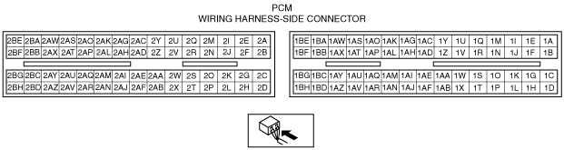
PCM INSPECTION [L8, LF]
id0140i7802500
Not Using the M-MDS
amxzzw00000023
|
|
Terminal |
Signal |
Connected to |
Test condition |
Voltage (V) |
Inspection item |
|
|---|---|---|---|---|---|---|
|
1A
|
—
|
—
|
—
|
—
|
—
|
|
|
1B
|
Starter relay control
|
Starter relay
|
Under any condition
|
Below 1.0
|
• Starter relay
• Related wiring harness
|
|
|
1C
|
—
|
—
|
—
|
—
|
—
|
|
|
1D*1
|
Clutch operation
|
CPP switch
|
Clutch pedal depressed
|
Below 1.0
|
• CPP switch
• Related wiring harness
|
|
|
Clutch pedal released
|
B+
|
|||||
|
1E
|
—
|
—
|
—
|
—
|
—
|
|
|
1F
|
—
|
—
|
—
|
—
|
—
|
|
|
1G
|
—
|
—
|
—
|
—
|
—
|
|
|
1H
|
Fuel pump control
|
Fuel pump relay
|
Ignition switch is turned to the ON position (Engine off) and a certain period has elapsed
|
B+
|
• Fuel pump relay
• Related wiring harness
|
|
|
Cranking
|
Below 1.0
|
|||||
|
Idle
|
Below 1.0
|
|||||
|
1I
|
A/C
|
A/C relay
|
Engine running
|
A/C operating
|
Below 1.0
|
• A/C relay
• Related wiring harness
|
|
A/C not operating
|
B+
|
|||||
|
1J
|
Refrigerant pressure switch (middle)
|
Refrigerant pressure switch (middle)
|
Refrigerant pressure is more than the specification. (Refrigerant pressure switch (middle) is on.)
|
Below 1.0
|
• Refrigerant pressure switch (middle)
• Related wiring harness
|
|
|
Refrigerant pressure is less than the specification. (Refrigerant pressure switch (middle) is off.)
|
B+
|
|||||
|
1K
|
—
|
—
|
—
|
—
|
—
|
|
|
1L
|
—
|
—
|
—
|
—
|
—
|
|
|
1M
|
Cooling fan control
|
Cooling fan relay No.1
|
Cooling fan not operating
|
B+
|
• Cooling fan relay No.1
• Related wiring harness
|
|
|
Cooling fan operating
|
Below 1.0
|
|||||
|
1N
|
Cooling fan control
|
Cooling fan relay No.2
|
Cooling fan not operating
|
B+
|
• Cooling fan relay No.2
• Related wiring harness
|
|
|
Cooling fan operating
|
Below 1.0
|
|||||
|
1O
|
—
|
—
|
—
|
—
|
—
|
|
|
1P
|
MAF sensor ground
|
MAF sensor
|
Under any condition
|
Below 1.0
|
• Related wiring harness
|
|
|
1Q
|
Main relay control
|
Main relay
|
Ignition switch is turned to the ON position
|
Below 1.0
|
• Main relay
• Related wiring harness
|
|
|
Ignition switch off and a certain period has elapsed
|
B+
|
|||||
|
1R
|
Cooling fan control
|
Cooling fan relay No.3
|
Cooling fan not operating
|
B+
|
• Cooling fan relay No.3
• Related wiring harness
|
|
|
Cooling fan operating
|
Below 1.0
|
|||||
|
1S
|
—
|
—
|
—
|
—
|
—
|
|
|
1T
|
—
|
—
|
—
|
—
|
—
|
|
|
1U
|
—
|
—
|
—
|
—
|
—
|
|
|
1V
|
—
|
—
|
—
|
—
|
—
|
|
|
1W
|
—
|
—
|
—
|
—
|
—
|
|
|
1X
|
Neutral position*1
|
Neutral switch
|
Shift lever is at neutral position
|
Below 1.0
|
• Neutral switch
• Related wiring harness
|
|
|
Shift lever is not at neutral position
|
B+
|
|||||
|
Selector lever position*2
|
TR switch
|
Ignition switch is turned to the ON position
|
P, N position
|
Below 1.0
|
• TR switch
• Related wiring harness
|
|
|
Except above
|
B+
|
|||||
|
1Y
|
—
|
—
|
—
|
—
|
—
|
|
|
1Z
|
—
|
—
|
—
|
—
|
—
|
|
|
1AA
|
—
|
—
|
—
|
—
|
—
|
|
|
1AB
|
Brake switch 1
|
Brake switch (No.1 signal)
|
Brake pedal depressed
|
B+
|
• Brake switch (No.1 signal)
• Related wiring harness
|
|
|
Brake pedal released
|
Below 1.0
|
|||||
|
1AC
|
—
|
—
|
—
|
—
|
—
|
|
|
1AD
|
—
|
—
|
—
|
—
|
—
|
|
|
1AE
|
—
|
—
|
—
|
—
|
—
|
|
|
1AF*5
|
Brake switch 2
|
Brake switch (No.2 signal)
|
Brake pedal depressed
|
B+
|
• Brake switch (No.2 signal)
• Related wiring harness
|
|
|
Brake pedal released
|
Below 1.0
|
|||||
|
1AG
|
—
|
—
|
—
|
—
|
—
|
|
|
1AH
|
—
|
—
|
—
|
—
|
—
|
|
|
1AI
|
CAN_L
|
CAN related module
|
Because this terminal is for CAN, no valid determination of terminal voltage is possible
|
• Related wiring harness
|
||
|
1AJ
|
APP sensor No.2 power supply
|
APP sensor
|
Ignition switch is turned to the ON position
|
Approx. 5.0
|
• Related wiring harness
|
|
|
1AK
|
MAF
|
MAF sensor
|
Ignition switch is turned to the ON position
|
Approx. 0.7
|
• MAF sensor
• Related wiring harness
|
|
|
Idle
|
Approx. 1.4
|
|||||
|
1AL
|
APP sensor No.1 power supply
|
APP sensor
|
Ignition switch is turned to the ON position.
|
Approx. 5.0
|
• Related wiring harness
|
|
|
1AM
|
CAN_H
|
CAN related module
|
Because this terminal is for CAN, no valid determination of terminal voltage is possible
|
• Related wiring harness
|
||
|
1AN
|
—
|
—
|
—
|
—
|
—
|
|
|
1AO
|
APP sensor No.1
|
APP sensor
|
Ignition switch is turned to the ON position
|
Accelerator pedal depressed
|
Approx. 3.9
|
• APP sensor
• Related wiring harness
|
|
Accelerator pedal released
|
Approx. 1.6
|
|||||
|
1AP
|
APP sensor No.2
|
APP sensor
|
Ignition switch is turned to the ON position
|
Accelerator pedal depressed
|
Approx. 3.4
|
• APP sensor
• Related wiring harness
|
|
Accelerator pedal released
|
Approx. 1.0
|
|||||
|
1AQ*3
|
Cruise control switch
|
Cruise control switch
|
Ignition switch is turned to the ON position
|
ON OFF switch pressed in
|
Approx. 0
|
• Cruise control switch
• Related wiring harness
|
|
CANCEL switch pressed in
|
Approx. 1.1
|
|||||
|
SET/– switch pressed in
|
Approx. 3.1
|
|||||
|
RES/+ switch pressed in
|
Approx. 4.2
|
|||||
|
Except above
|
Approx. 5.0
|
|||||
|
1AR
|
Sensor ground
|
MAF/IAT sensor
|
Under any condition
|
Below 1.0
|
• Related wiring harness
|
|
|
1AS
|
APP sensor No.1 ground
|
APP sensor
|
Under any condition
|
Below 1.0
|
• Related wiring harness
|
|
|
1AT
|
IAT
|
MAF/IAT sensor
|
Ignition switch is turned to the ON position
|
IAT is 20 °C {68 °F}
|
Approx. 2.4
|
• IAT sensor
• Related wiring harness
|
|
IAT is 60°C {140 °F}
|
Approx. 0.9
|
|||||
|
1AU
|
Refrigerant pressure switch (high, low)
|
Refrigerant pressure switch (high, low)
|
Ignition switch is turned to the ON position
|
A/C operating
|
Below 1.0
|
• Refrigerant pressure switch (high, low)
• Related wiring harness
|
|
A/C not operating
|
B+
|
|||||
|
1AV
|
APP sensor No.2 ground
|
APP sensor
|
Under any condition
|
Below 1.0
|
• Related wiring harness
|
|
|
1AW
|
B+
|
Main relay
|
Ignition switch off
|
Below 1.0
|
• Main relay
• Related wiring harness
|
|
|
Ignition switch is turned to the ON position
|
B+
|
|||||
|
1AX
|
Drive-by-wire relay control
|
Drive-by-wire relay
|
Under any condition
|
Below 1.0
|
• Drive-by-wire relay
• Related wiring harness
|
|
|
1AY
|
Ignition switch
|
Ignition switch
|
Ignition switch off
|
Below 1.0
|
• Ignition switch
• Related wiring harness
|
|
|
Ignition switch is turned to the ON position
|
B+
|
|||||
|
1AZ
|
Ground
|
Ground
|
Under any condition
|
Below 1.0
|
• Related wiring harness
|
|
|
1BA
|
Back-up power supply
|
Battery (positive terminal)
|
Under any condition
|
B+
|
• Battery
• Related wiring harness
|
|
|
1BB
|
Ground
|
Ground
|
Under any condition
|
Below 1.0
|
• Related wiring harness
|
|
|
1BC
|
—
|
—
|
—
|
—
|
—
|
|
|
1BD
|
Ground
|
Ground
|
Under any condition
|
Below 1.0
|
• Related wiring harness
|
|
|
1BE
|
B+
|
Main relay
|
Ignition switch off
|
Below 1.0
|
• Main relay
• Related wiring harness
|
|
|
Ignition switch is turned to the ON position
|
B+
|
|||||
|
1BF
|
Drive-by-wire relay control
|
Drive-by-wire relay
|
Ignition switch is turned to the ON position
|
Drive-by-wire system is malfunction
|
Below 1.0
|
• Drive-by-wire relay
• Related wiring harness
|
|
Drive-by-wire system is normal
|
B+
|
|||||
|
1BG
|
—
|
—
|
—
|
—
|
—
|
|
|
1BH
|
Ground
|
Ground
|
Under any condition
|
Below 1.0
|
• Related wiring harness
|
|
|
2A
|
Throttle control (+)
|
Throttle body (Throttle valve actuator)
|
• Inspect using the wave profile.
|
• Throttle valve actuator
• Related wiring harness
|
||
|
2B
|
Throttle control (–)
|
Throttle body (Throttle valve actuator)
|
• Inspect using the wave profile.
|
• Throttle valve actuator
• Related wiring harness
|
||
|
2C
|
Purge control
|
Purge solenoid valve
|
• Inspect using the wave profile.
|
• Purge solenoid valve
• Related wiring harness
|
||
|
2D
|
—
|
—
|
—
|
—
|
—
|
|
|
2E*4
|
OCV control
|
OCV
|
• Inspect using the wave profile.
|
• OCV
• Related wiring harness
|
||
|
2F
|
—
|
—
|
—
|
—
|
—
|
|
|
2G
|
EGR valve #2 coil control
|
EGR valve
|
Idle (EGR control not operating)
|
B+
|
• EGR valve
• Related wiring harness
|
|
|
2H
|
EGR valve #4 coil control
|
EGR valve
|
Idle (EGR control not operating)
|
B+
|
• EGR valve
• Related wiring harness
|
|
|
2I
|
Variable tumble control
|
Variable tumble solenoid valve
|
ECT 60 °C {142 °F} or more and engine speed 3,750 rpm or more
|
B+
|
• Variable tumble solenoid valve
• Related wiring harness
|
|
|
ECT less than 60 °C {142 °F} and engine speed less than 3,750 rpm
|
Below 1.0
|
|||||
|
2J
|
Variable intake air control
|
Variable intake air solenoid valve
|
Ignition switch is turned to the ON position
|
Below 1.0
|
• Variable intake air solenoid valve
• Related wiring harness
|
|
|
Engine speed: less than 4,750 rpm
|
Below 1.0
|
|||||
|
Engine speed: 4,750 rpm or more
|
B+
|
|||||
|
2K
|
EGR valve #1 coil control
|
EGR valve
|
Idle (EGR control not operating)
|
Below 1.0
|
• EGR valve
• Related wiring harness
|
|
|
2L
|
EGR valve #3 coil control
|
EGR valve
|
Idle (EGR control not operating)
|
B+
|
• EGR valve
• Related wiring harness
|
|
|
2M
|
—
|
—
|
—
|
—
|
—
|
|
|
2N
|
—
|
—
|
—
|
—
|
—
|
|
|
2O
|
—
|
—
|
—
|
—
|
—
|
|
|
2P
|
CMP sensor ground
|
CMP sensor
|
Under any condition
|
Below 1.0
|
• Related wiring harness
|
|
|
2Q
|
HO2S
|
HO2S
|
Idle after warm-up
|
Alternates between 0 and 1.0
|
• HO2S
• Related wiring harness
|
|
|
2R
|
—
|
—
|
—
|
—
|
—
|
|
|
2S
|
CMP
|
CMP sensor
|
• Inspect using the wave profile.
|
• CMP sensor
• Related wiring harness
|
||
|
2T
|
Power steering pressure
|
PSP switch
|
Idle
|
Steering wheel at straight ahead position
|
B+
|
• PSP switch
• Related wiring harness
|
|
While turning steering wheel
|
Below 1.0
|
|||||
|
2U
|
Knocking (+)
|
KS
|
Ignition switch ON (Use digital type voltmeter, because measurement voltage will be detected less than true voltage when using analog type voltmeter)
|
Approx. 4.3
|
• KS
• Related wiring harness
|
|
|
2V
|
Knocking (–)
|
KS
|
Ignition switch ON (Use digital type voltmeter, because measurement voltage will be detected less than true voltage when using analog type voltmeter)
|
Below 1.0
|
• KS
• Related wiring harness
|
|
|
2W
|
CKP
|
CKP sensor
|
• Inspect using the wave profile.
|
• CKP sensor
• Related wiring harness
|
||
|
2X
|
Ground
|
Shield wire
|
Under any condition
|
Below 1.0
|
• Related wiring harness
|
|
|
2Y
|
—
|
—
|
—
|
—
|
—
|
|
|
2Z
|
A/F sensor
|
A/F sensor
|
Idle after warm-up
|
Approx. 2.4
|
• A/F sensor
• Related wiring harness
|
|
|
2AA
|
—
|
—
|
—
|
—
|
—
|
|
|
2AB
|
CKP sensor ground
|
CKP sensor
|
Under any condition
|
Below 1.0
|
• Related wiring harness
|
|
|
2AC
|
—
|
—
|
—
|
—
|
—
|
|
|
2AD
|
A/F sensor
|
A/F sensor
|
Idle after warm-up
|
Approx. 2.8
|
• A/F sensor
• Related wiring harness
|
|
|
2AE
|
—
|
—
|
—
|
—
|
—
|
|
|
2AF
|
—
|
—
|
—
|
—
|
—
|
|
|
2AG
|
Manifold absolute pressure
|
MAP sensor
|
Ignition switch is turned to the ON position (at sea level)
|
Approx. 4.1
|
• MAP sensor
• Related wiring harness
|
|
|
Idle
|
Approx. 1.2
|
|||||
|
2AH
|
ECT
|
ECT sensor
|
Ignition switch is turned to the ON position
|
ECT is 20 °C {68 °F}
|
Approx. 3.0
|
• ECT sensor
• Related wiring harness
|
|
ECT is 80 °C {176 °F}
|
Approx. 0.9
|
|||||
|
2AI
|
Generator field coil control
|
Generator
(terminal D)
|
• Inspect using the wave profile.
|
• Generator
• Related wiring harness
|
||
|
2AJ
|
Generator output voltage
|
Generator
(terminal P)
|
• Inspect using the wave profile.
|
• Generator
• Related wiring harness
|
||
|
2AK
|
Throttle valve opening angle No. 1
|
Throttle body (TP sensor)
|
Ignition switch is turned to the ON position
|
Accelerator pedal depressed
|
Approx. 4.5
|
• TP sensor
• Related wiring harness
|
|
Accelerator pedal released
|
Approx. 0.5
|
|||||
|
2AL
|
Throttle valve opening angle No. 2
|
Throttle body (TP sensor)
|
Ignition switch is turned to the ON position
|
Accelerator pedal depressed
|
Approx. 0.5
|
• TP sensor
• Related wiring harness
|
|
Accelerator pedal released
|
Approx. 4.5
|
|||||
|
2AM
|
Constant voltage
|
CMP sensor
|
Ignition switch is turned to the ON position
|
B+
|
• Related wiring harness
|
|
|
2AN
|
—
|
—
|
—
|
—
|
—
|
|
|
2AO
|
Constant voltage (Vref)
|
Throttle body (TP sensor)
|
Ignition switch is turned to the ON position
|
Approx. 5.0
|
• Related wiring harness
|
|
|
2AP
|
Sensor ground
|
Throttle body (TP sensor)
|
Under any condition
|
Below 1.0
|
• Related wiring harness
|
|
|
2AQ
|
Constant voltage
|
CKP sensor
|
Ignition switch is turned to the ON position
|
B+
|
• Related wiring harness
|
|
|
2AR
|
—
|
—
|
—
|
—
|
—
|
|
|
2AS
|
—
|
—
|
—
|
—
|
—
|
|
|
2AT
|
IGT4
|
Ignition coil (No.4 cylinders)
|
• Inspect using the wave profile.
|
• Ignition coil No.4
• Related wiring harness
|
||
|
2AU
|
Constant voltage (Vref)
|
MAP sensor
|
Ignition switch is turned to the ON position
|
Approx. 5.0
|
• Related wiring harness
|
|
|
2AV
|
MAP sensor ground
|
MAP sensor
|
Under any condition
|
Below 1.0
|
• Related wiring harness
|
|
|
2AW
|
IGT2
|
Ignition coil (No.2 cylinders)
|
• Inspect using the wave profile.
|
• Ignition coil No.2
• Related wiring harness
|
||
|
2AX
|
IGT3
|
Ignition coil (No.3 cylinders)
|
• Inspect using the wave profile.
|
• Ignition coil No.3
• Related wiring harness
|
||
|
2AY
|
ECT sensor ground
|
ECT sensor
|
Under any condition
|
Below 1.0
|
• Related wiring harness
|
|
|
2AZ
|
Fuel injection (#4)
|
Fuel injector No.4
|
• Inspect using the wave profile.
|
• Fuel injector No.4
• Related wiring harness
|
||
|
2BA
|
IGT1
|
Ignition coil (No.1 cylinders)
|
• Inspect using the wave profile.
|
• Ignition coil No.1
• Related wiring harness
|
||
|
2BB
|
Fuel injection (#1)
|
Fuel injector No.1
|
• Inspect using the wave profile.
|
• Fuel injector No.1
• Related wiring harness
|
||
|
2BC
|
Fuel injection (#2)
|
Fuel injector No.2
|
• Inspect using the wave profile.
|
• Fuel injector No.2
• Related wiring harness
|
||
|
2BD
|
Fuel injection (#3)
|
Fuel injector No.3
|
• Inspect using the wave profile.
|
• Fuel injector No.3
• Related wiring harness
|
||
|
2BE
|
HO2S heater control
|
HO2S heater
|
Heavy load (Heater control not operating)
|
B+
|
• HO2S heater
• Related wiring harness
|
|
|
2BF
|
—
|
—
|
—
|
—
|
—
|
|
|
2BG
|
A/F sensor heater control
|
A/F sensor heater
|
• Inspect using the wave profile.
|
• A/F sensor heater
• Related wiring harness
|
||
|
2BH
|
HO2S ground
|
HO2S
|
Under any condition
|
Below 1.0
|
• Related wiring harness
|
|
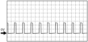
Inspection Using An Oscilloscope (Reference)
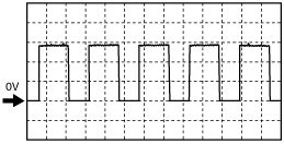
Throttle control (+) signal
amxzzw00000024
|
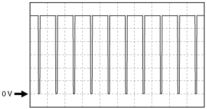
Throttle control (–) signal
amxzzw00000025
|
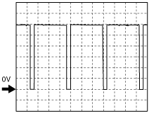
Purge control signal
amxzzw00000026
|
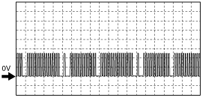
OCV control signal
amxzzw00000027
|
CMP signal
amxzzw00000028
|
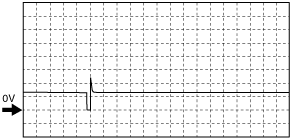
CKP signal
amxzzw00000029
|
Generator field coil control signal
amxzzw00000030
|
Generator output voltage signal
amxzzw00000031
|
Ignition timing signals
amxzzw00000032
|
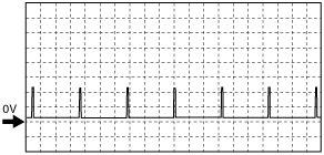
Fuel injection signals
amxzzw00000033
|
A/F sensor heater control signal
amxzzw00000034
|
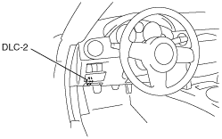
Using the M-MDS
1. Connect the SST (M-MDS) to the DLC-2.
amxzzw00000035
|
2. Turn the ignition switch to ON position.
3. Measure the PID value.
PID/DATA monitor table (reference)
|
Item (definition) |
Unit/Condition |
Condition/Specification (Reference) |
Inspection item(s) |
PCM terminal |
|||
|---|---|---|---|---|---|---|---|
|
AC_REQ
(Refrigerant pressure switch (high, low)
|
Off/On
|
• Refrigerant pressure is more than the specification or less than the specification. (Refrigerant pressure switch (high, low) is off.): Off
• Except above: On
|
• Refrigerant pressure switch (high, low)
• A/C amplifier
|
1AU
|
|||
|
ACCS
(A/C relay)
|
Off/On
|
• A/C relay is ON: On
• A/C relay is OFF: Off
|
• The following PIDs
• A/C relay
|
1I
|
|||
|
AFR
(Air/fuel ratio)
|
-
|
• Idle after warm-up: Approx. 1
|
• A/F sensor
|
2Z,
2AD
|
|||
|
AFR_ACT
(Actual air/fuel ratio)
|
-
|
• Idle after warm-up: Approx. 1
|
• A/F sensor
• HO2S
|
—
|
|||
|
ALTF
(Generator field coil control duty value)
|
%
|
• Ignition switch is turned to the ON position: 0%
• Idle, E/L is operating: Duty value increases.
|
• Generator
|
2AI
|
|||
|
ALTT V
(Generator output voltage)
|
V
|
• Idle (no E/L): Approx. 14 V (This is an internal calculation value and differs from the terminal voltage.)
|
• Generator
|
2AJ
|
|||
|
APP
(Accelerator pedal position)
|
%
|
• Accelerator pedal released: 0%
• Accelerator pedal depressed: 100%
|
• The following PIDs
|
1AO, 1AP
|
|||
|
APP1
(APP sensor No.1)
|
%
|
• Accelerator pedal released: Approx. 32%
• Accelerator pedal depressed: Approx. 78%
|
• APP sensor
|
1AO
|
|||
|
V
|
• Accelerator pedal released: Approx. 1.6 V
• Accelerator pedal depressed: Approx. 3.9 V
|
||||||
|
APP2
(APP sensor No.2)
|
%
|
• Accelerator pedal released: Approx. 21%
• Accelerator pedal depressed: Approx. 67%
|
• APP sensor
|
1AP
|
|||
|
V
|
• Accelerator pedal released: Approx. 1.0 V
• Accelerator pedal depressed: Approx. 3.4 V
|
||||||
|
ARPMDES
(Target engine speed)
|
RPM
|
• Indicate the target engine speed.
|
• The following PIDs
|
—
|
|||
|
BARO
(Barometric pressure)
|
Pa
|
• Indicate the barometric pressure
|
—
|
—
|
|||
|
V
|
• Ignition switch is turned to the ON position (at sea level): 4.1 V
|
||||||
|
BOO
(Brake switch (No.1 signal))
|
On/Off
|
• Brake pedal depressed: ON
• Brake pedal released: OFF
|
• Brake switch (No.1 signal)
|
1AB
|
|||
|
BPA*5
(Brake switch (No.2 signal))
|
On/Off
|
• Brake pedal depressed: ON
• Brake pedal released: OFF
|
• Brake switch (No.2 signal)
|
1AF
|
|||
|
CATT11_DSD
(Catalyst temperature)
|
°C
|
°F
|
• Indicate the catalyst temperature
|
—
|
—
|
||
|
CHRGLP
(Generator warning light)
|
Off/On
|
• Idle, Generator warning light illuminate: On
• Idle, Generator warning light not illuminate: Off
|
• Generator warning light
|
—
|
|||
|
COLP
(Refrigerant pressure switch (middle))
|
OFF/ON
|
• Refrigerant pressure is more than the specification. (Refrigerant pressure switch (middle) is on.): On
• Refrigerant pressure is less than the specification. (Refrigerant pressure switch (middle) is off.): Off
|
• Refrigerant pressure switch (middle)
|
1J
|
|||
|
CPP*1
(Clutch pedal position)
|
Off/On
|
• Clutch pedal depressed: On
• Clutch pedal released: Off
|
• CPP switch
|
1D
|
|||
|
CPP/PNP*1
(Shift lever position)
|
Drive/Neutral
|
• Neutral: Neutral
• Other than neutral: Drive
|
• Neutral switch
|
1X
|
|||
|
DTCCNT
(Number of DTC detected)
|
—
|
• Number of DTCs stored
|
—
|
—
|
|||
|
ECT
(Engine coolant temperature)
|
°C
|
°F
|
• Indicate the ECT
|
• ECT sensor
|
2AH
|
||
|
V
|
• ECT is 20 °C {68 °F}: Approx. 3.0 V
• ECT is 80 °C {176 °F}: Approx. 0.9 V
|
||||||
|
EQ_RAT11
(Actual lambda signal)
|
—
|
• Idle after warm-up: Approx. 1
|
• A/F sensor
|
—
|
|||
|
EQ_RAT11_DSD
(Target lambda)
|
—
|
• Target lambda (Excess air factor = supplied air amount / theoretical air/fuel ratio)
|
• A/F sensor
|
—
|
|||
|
ETC_ACT
(Throttle control)
|
°
|
• Accelerator pedal released: Approx. 0 °
• Accelerator pedal depressed: Approx. 94.5 °
|
• Throttle valve actuator
|
2A,
2B
|
|||
|
ETC_DSD
(Throttle control desired)
|
%
|
• Indicate the target throttle valve opening ratio
|
• The following PIDs
|
—
|
|||
|
°
|
• Indicate the target throttle valve opening angle
|
||||||
|
EVAPCP
(Purge solenoid valve duty value)
|
%
|
• Ignition switch is turned to the ON position: 0%
• Increase the engine speed (after warm-up): Duty value rises
|
• The following PIDs
• Purge solenoid valve
|
2C
|
|||
|
FAN1
(Cooling fan relay No.1 control signal)
|
Off/On
|
• During test mode
CTP: Off
WOT: On
|
• The following PIDs
• Cooling fan relay No.1
|
1M
|
|||
|
FAN2
(Cooling fan relay No.2 control signal)
|
Off/On
|
• During test mode
CTP: Off
WOT: On
|
• The following PIDs
• Cooling fan relay No.2
|
1N
|
|||
|
FAN3
(Cooling fan relay No.3 control signal)
|
Off/On
|
• During test mode
CTP: Off
WOT: On
|
• The following PIDs
• Cooling fan relay No.3
|
1R
|
|||
|
FP
(Fuel pump relay)
|
Off/On
|
• Ignition switch is turned to the ON position and a certain period has elapsed: Off
• Cranking: On
• Idle: On
|
• Fuel pump relay
|
1H
|
|||
|
FUELPW
(Fuel injector duration)
|
sec
|
• Idle: Approx. 2.0 ms
|
• The following PIDs
• Fuel injector
|
2BB, 2BC, 2BD, 2AZ
|
|||
|
FUELSYS
(Fuel system status)
|
OL/CL/
OL–Drive/
OL–Fault/
CL–Fault
|
• Idle after warm-up: CL
|
• The following PIDs
|
—
|
|||
|
GENVDSD
(Target generator voltage)
|
V
|
• Indicate the target generated voltage
|
• The following PIDs
• Generator
|
—
|
|||
|
HTR11
(A/F sensor heater control)
|
Off/On
|
• Ignition switch is turned to the ON position: Off
• Idle: On
|
• The following PIDs
• A/F sensor heater
|
2BG
|
|||
|
HTR12
(HO2S heater control)
|
Off/On
|
• Ignition switch is turned to the ON position: Off
• Idle: On
|
• The following PIDs
• HO2S heater
|
2BE
|
|||
|
IAT
(Intake air temperature)
|
°C
|
°F
|
• Indicate the IAT
|
• IAT sensor
|
1AT
|
||
|
V
|
• IAT is 20 °C {68 °F}: Approx. 2.4 V
• IAT is 60 °C {140 °F}: Approx. 0.9 V
|
||||||
|
IMRC*4
(Variable tumble control)
|
Off/On
|
• ECT less than 60 °C {142 °F} and engine speed less than 3,750 rpm: On
• ECT 60 °C {142 °F} or more and engine speed 3,750 rpm or more: Off
|
• The following PIDs
• Variable sllenoid valve
|
2I
|
|||
|
IMTV
(Variable intake air control)
|
Off/On
|
• Engine speed is less than 4,750 rpm: On
• Engine speed is 4,750 rpm or more: Off
|
• The following PIDs
• Variadle intake air solenoid valve
|
2J
|
|||
|
INGEAR
(Gears are engaged)
|
Off/On
|
MT
• When the following conditions are satisfied: On
• Except above: Off
|
• CPP switch
• Neutral switch
|
1D,1X
|
|||
|
AT
• Driving range: On
• Except above: Off
|
• TR switch
|
1X
|
|||||
|
IVS
(CTP condition)
|
Idle/Off Idle
|
• Idle: Idle
• Other than idle: Off Idle
|
• The following PIDs
|
—
|
|||
|
KNOCKR
(Knocking retard)
|
°
|
• Ignition switch is turned to the ON position: 0 °
• Idle: 0 °
|
• KS
|
2U,
2V
|
|||
|
LOAD
(Engine load)
|
%
|
• Idle after warm-up: Approx. 23%
|
• The following PIDs
|
—
|
|||
|
LONGFT1
(Long term fuel trim)
|
%
|
• Idle after warm-up: Approx. –15—+15%
|
• The following PIDs
|
—
|
|||
|
MAF
(Mass air flow)
|
g/sec
|
• Indicate the MAF
|
• MAF sensor
|
1AK
|
|||
|
V
|
• Ignition switch is turned to the ON position: Approx. 0.7 V
• Idle: Approx. 1.4 V
|
||||||
|
MAP
(Manifold absolute pressure)
|
Pa
|
• Indicate the MAP
|
• MAP sensor
|
2AG
|
|||
|
V
|
• Ignition switch is turned to the ON position (at sea level): 4.1 V
• Idle after warm-up: Approx. 1.2 V
|
||||||
|
MIL
(Malfunction indicator lamp)
|
Off/On
|
• Idle, MIL illuminate: On
• Idle, MIL not illuminate: Off
|
• MIL
|
—
|
|||
|
MIL_DIS
(Travelled distance since MIL illuminated)
|
km
|
mile
|
Travelled distance since MIL illuminated
|
—
|
|||
|
O2S11
(A/F sensor)
|
A
|
• Idle after warm-up: Approx. 0 mA
|
• A/F sensor
|
2AD
|
|||
|
O2S12
(HO2S)
|
V
|
• Idle after warm-up: Alternates between 0 and 1.0 V
|
• HO2S
|
2Q
|
|||
|
PSP
(PSP switch)
|
Low/High
|
• Steering wheel at straight ahead position: Low
• While turning steering wheel: High
|
• PSP switch
|
2T
|
|||
|
RO2FT1
(HO2S fuel trim)
|
—
|
• Idle after warm-up: Approx. 0
|
• The following PIDs
|
—
|
|||
|
RPM
(Engine speed)
|
RPM
|
• When the engine is running: Indicate the engine speed
|
• CKP sensor
|
2W
|
|||
|
SCCS*2
(Cruise control switch)
|
V
|
• ON OFF switch pressed in: Approx. 0 V
• CANCEL switch pressed in: Approx. 1.1 V
• SET/- switch pressed in: Approx. 3.1 V
• RES/+ switch pressed in: Approx. 4.2 V
• Except above: Approx. 5.0 V
|
• Cruise control switch
|
1AQ
|
|||
|
SEGRP
(EGR control)
|
—
|
• Ignition switch is turned to the ON position: 0 Step
• Idle: 0 Step
• Engine speed is 1,187—4,200 rpm: 0—52 Step
|
• EGR valve
|
2K, 2G, 2L, 2H
|
|||
|
SEGRP DSD
(EGR valve position desired)
|
%
|
• Ignition switch is turned to the ON position: 0%
• Idle: 0%
• Engine speed is 1,187—4,200 rpm: 0—100%
|
• The following PIDs
|
—
|
|||
|
SHRTFT1
(Short term fuel trim (front))
|
%
|
• Idle after warm-up: –25— 25%
|
• The following PIDs
|
—
|
|||
|
SPARKADV
(Ignition timing)
|
°
|
• Indicate the ignition timing
|
• The following PIDs
• Ignition coil
|
2S
|
|||
|
test
(Test mode)
|
Off/On
|
• Test mode On: On
• Test mode Off: Off
|
—
|
—
|
|||
|
TIRESIZE
(Tire revolution per mile)
|
rev/mile
|
• Indicate the tire revolution per a mile
|
—
|
||||
|
TP REL
(Throttle position signal (relative value))
|
%
|
• Accelerator pedal released: Approx. 10%
• Accelerator pedal depressed: Approx. 81%
|
• The following PIDs
|
2AK,
2AL
|
|||
|
TP1
(TP sensor No.1)
|
%
|
• Accelerator pedal released: Approx. 10%
• Accelerator pedal depressed: Approx. 90%
|
• TP sensor
|
2AK
|
|||
|
V
|
• Accelerator pedal released: Approx. 0.5 V
• Accelerator pedal depressed: Approx. 4.5 V
|
||||||
|
TP2
(TP sensor No.2)
|
%
|
• Accelerator pedal released: Approx. 10%
• Accelerator pedal depressed: Approx. 90%
|
• TP sensor
|
2AL
|
|||
|
V
|
• Accelerator pedal released: Approx. 4.5 V
• Accelerator pedal depressed: 0.5 V
|
||||||
|
TPCT
(TP sensor voltage at CTP)
|
V
|
• Ignition switch is turned to the ON position: Approx. 0.5 V
|
• The following PIDs
|
—
|
|||
|
VPWR
(Battery positive voltage)
|
V
|
• Indicate the battery voltage
|
• Battery
|
1BA
|
|||
|
VSS
(Vehicle speed)
|
KPH
|
• Vehicle running: Indicate the vehicle speed
|
• ABS, DSC HU/CM
|
—
|
|||
|
VT ACT1*3
(Actual valve timing)
|
°
|
• Idle: Approx. 0 °
• Racing: 0—25 °
|
• The following PIDs
• CMP sensor
|
2S
|
|||
|
VT DIFF1*3
(Difference between target valve timing and actual valve timing)
|
°
|
• Idle: 0 °
|
• The following PIDs
• OCV
|
—
|
|||
|
VT DUTY1*3
(OCV control)
|
%
|
• Idle: Approx. 10%
|
• The following PIDs
|
2E
|
|||