Note
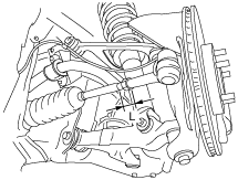
• Rotate and adjust the tie rod. The difference between the right and left dimension L shown in the figure should be within the specification.
amxzzw00000757
|
FRONT WHEEL ALIGNMENT
id021100800200
Front wheel alignment [16-inch wheel]
|
Item |
Specification |
||
|---|---|---|---|
|
Total toe-in
|
Tire [Tolerance ±4 mm {0.15 in}]
|
(mm {in})
|
1.6 {0.063}
|
|
Rim inner
|
(mm {in})
|
1.1±2.6 {0.04±0.10}
|
|
|
|
degree
|
0°09′±22′
|
|
|
Steering angle [Tolerance ±3°]
|
Inner
|
38°42′
|
|
|
Outer
|
32°54′
|
||
|
Steering axis inclination (Reference value)
|
10°57′
|
||
|
Camber
[Tolerance ±1°]
|
Vehicle height: From the end of the front fender to the center of the wheel (mm {in})
|
356—365 {14.1—14.3}
|
-0°34′
|
|
366—375 {14.5—14.7}
|
-0°19′
|
||
|
376—385 {14.8—15.1}
|
-0°07′
|
||
|
386—395 {15.2—15.5}
|
0°04′
|
||
|
396—405 {15.6—15.9}
|
0°12′
|
||
|
Caster
[Tolerance ±1°]
|
Vehicle height: From the end of the rear fender to the center of the wheel (mm {in})
|
354—363 {14.0—14.2}
|
6°24′
|
|
364—373 {14.4—14.6}
|
6°10′
|
||
|
374—383 {14.8—15.0}
|
5°56′
|
||
|
384—393 {15.2—15.4}
|
5°43′
|
||
|
394—403 {15.6—15.8}
|
5°29′
|
||
Front wheel alignment [17-inch wheel]
|
Item |
Specification |
||
|---|---|---|---|
|
Total toe-in
|
Tire [Tolerance ±4 mm {0.15 in}]
|
(mm {in})
|
1.6 {0.063}
|
|
Rim inner
|
(mm {in})
|
1.1±2.8 {0.04±0.11}
|
|
|
degree
|
0°09′±22′
|
||
|
Steering angle [Tolerance ±3°]
|
Inner
|
38°42′
|
|
|
Outer
|
32°54′
|
||
|
Steering axis inclination (Reference value)
|
11°04′
|
||
|
Camber
[Tolerance ±1°]
|
Vehicle height: From the end of the front fender to the center of the wheel (mm {in})
|
351—360 {13.8—14.1}
|
-0°42′
|
|
361—370 {14.3—14.5}
|
-0°26′
|
||
|
371—380 {14.7—14.9}
|
-0°13′
|
||
|
381—390 {15.0—15.3}
|
-0°01′
|
||
|
391—400 {15.4—15.7}
|
0°08′
|
||
|
Caster
[Tolerance ±1°]
|
Vehicle height: From the end of the rear fender to the center of the wheel (mm {in})
|
349—358 {13.8—14.0}
|
6°32′
|
|
359—368 {14.2—14.4}
|
6°18′
|
||
|
369—378 {14.6—14.8}
|
6°04′
|
||
|
379—388 {15.0—15.2}
|
5°50′
|
||
|
389—398 {15.4—15.6}
|
5°36′
|
||
Steering Angle Adjustment
1. Loosen the locknut of the tie-rod end.
2. Remove the rack boot clamp.
3. Rotate the tie rod and adjust the steering angle.
amxzzw00000757
|
4. Tighten the locknut of the tie-rod end.
5. Correct the rack boot deformation.
6. Install and fix the rack boot clamp.
7. After adjusting the steering angle, always inspect and adjust the total toe-in. (See Total Toe-in Adjustment.)
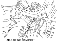
Camber Adjustment
1. Loosen the fixing nut of the adjusting cam bolt (front lower arm front side).
chu0211w006
|
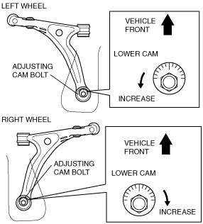
2. Rotate the adjusting cam bolt in either direction to adjust the camber.
e5u211zw5001
|
Vehicle equipped with 16-inch wheel
|
Vehicle height* |
Camber |
|---|---|
|
356—365 {14.1—14.3}
|
-0°34′
|
|
366—375 {14.5—14.7}
|
-0°19′
|
|
376—385 {14.8—15.1}
|
-0°07′
|
|
386—395 {15.2—15.5}
|
0°04′
|
|
396—405 {15.6—15.9}
|
0°12′
|
Vehicle equipped with 17-inch wheel
|
Vehicle height* |
Camber |
|---|---|
|
351—360 {13.8—14.1}
|
-0°42′
|
|
361—370 {14.3—14.5}
|
-0°26′
|
|
371—380 {14.7—14.9}
|
-0°13′
|
|
381—390 {15.0—15.3}
|
0°01′
|
|
391—400 {15.4—15.7}
|
0°08′
|
|
|
Left wheel |
Right wheel |
|---|---|---|
|
Positive direction
|
Clockwise
|
Counterclockwise
|
|
Negative direction
|
Counterclockwise
|
Clockwise
|
3. Tighten the nut.
4. Adjust the total toe-in. (See Total Toe-in Adjustment.)
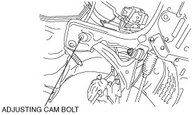
Caster Adjustment
1. Loosen the installation nut of the adjusting cam bolt (front lower arm rear side).
chu0211w027
|
2. Rotate the adjusting cam bolt in either direction to adjust the caster.
chu0211w022
|
Vehicle equipped with 16-inch wheel
|
Vehicle height* |
Caster |
|---|---|
|
354—363 {14.0—14.2}
|
6°24′
|
|
364—373 {14.4—14.6}
|
6°10′
|
|
374—383 {14.8—15.0}
|
5°56′
|
|
384—393 {15.2—15.4}
|
5°43′
|
|
394—403 {15.6—15.8}
|
5°29′
|
Vehicle equipped with 17-inch wheel
|
Vehicle height* |
Caster |
|---|---|
|
349—358 {13.8—14.0}
|
6°32′
|
|
359—368 {14.2—14.4}
|
6°18′
|
|
369—378 {14.6—14.8}
|
6°04′
|
|
379—388 {15.0—15.2}
|
5°50′
|
|
389—398 {15.4—15.6}
|
5°36′
|
|
|
Left wheel |
Right wheel |
|---|---|---|
|
Increase
|
Counterclockwise
|
Clockwise
|
|
Decrease
|
Clockwise
|
Counterclockwise
|
3. Tighten the nut.
4. Adjust the camber and total toe-in. (See Total Toe-in Adjustment.)
Total Toe-in Adjustment
1. Loosen the locknut of the tie-rod end.
2. Remove the rack boot clamp.
3. Adjust the total toe-in by rotating each tie rod (left and right) in the opposite directions by the same amount respectively.
4. Tighten the locknut of the tie-rod end.
5. Verify that the rack boot does not have any twisting, and install the rack boot clamp.