DTC C1145, C1155, C1165, C1175 [ABS]


id0402a7801100

DTC
C1145
C1155
C1165
C1175
RF ABS wheel-speed sensor (open circuit) system
LF ABS wheel-speed sensor (open circuit) system
RR ABS wheel-speed sensor (open circuit) system
LR ABS wheel-speed sensor (open circuit) system
DETECTION CONDITION
•  Open circuit or short to ground has been detected in the ABS wheel-speed sensor wiring harness on any of the four vehicle wheels.
POSSIBLE CAUSE
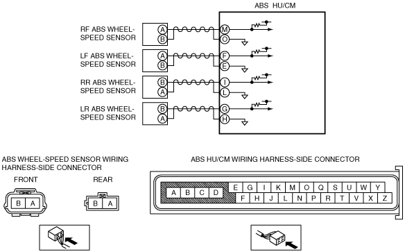
•  Open circuit or short to ground in the wiring harness between the following ABS HU/CM terminal and the ABS wheel-speed sensor terminal:
―  ABS HU/CM terminal M—RF ABS wheel-speed sensor terminal A
―  ABS HU/CM terminal O—RF ABS wheel-speed sensor terminal B
―  ABS HU/CM terminal F—LF ABS wheel-speed sensor terminal A
―  ABS HU/CM terminal E—LF ABS wheel-speed sensor terminal B
―  ABS HU/CM terminal I—RR ABS wheel-speed sensor terminal B
―  ABS HU/CM terminal L—RR ABS wheel-speed sensor terminal A
―  ABS HU/CM terminal G—LR ABS wheel-speed sensor terminal B
―  ABS HU/CM terminal H—LR ABS wheel-speed sensor terminal A
•  ABS wheel-speed sensor malfunction
•  Poor connection at connectors (female terminal)

Diagnostic procedure

STEP

INSPECTION

ACTION

1
INSPECT PID TO VERIFY THAT WHEEL SPEED-SIGNALS ARE TRANSMITTED FROM ABS WHEEL- SPEED SENSOR USING M-MDS
•  Turn the ignition switch to the LOCK position.
•  Connect the M-MDS to the DLC-2.
•  Select the following PIDs using the M-MDS:
―  LF_WSPD
―  LR_WSPD
―  RF_WSPD
―  RR_WSPD
•  Drive the vehicle.
•  Verify that the wheel speed-signals are transmitted from each ABS wheel-speed sensor.
•  Are the wheel-speed signals transmitted?
Yes
Go to Step 3.
No
Go to the next step.
2
INSPECT FOR OPEN CIRCUIT IN WIRING HARNESS BETWEEN ABS HU/CM AND ABS WHEEL-SPEED SENSOR
•  Turn the ignition switch to the LOCK position.
•  Disconnect the ABS HU/CM connector and ABS wheel-speed sensor.
•  Inspect for continuity in the wiring harness between the following ABS wheel-speed sensor connectors on the vehicle wiring harness-side and ABS HU/CM connectors.
―  RF ABS wheel-speed sensor (+): M—A
―  RF ABS wheel-speed sensor (–): O—B
―  LF ABS wheel-speed sensor (+): F—A
―  LF ABS wheel-speed sensor (–): E—B
―  RR ABS wheel-speed sensor (+): I—B
―  RR ABS wheel-speed sensor (–): L—A
―  LR ABS wheel-speed sensor (+): G—B
―  LR ABS wheel-speed sensor (–): H—A
•  Is there continuity?
Yes
Replace the ABS wheel-speed sensor, then go to the next step.
No
Repair or replace the wiring harness, then go to the next step.
3
VERIFY THAT THE SAME DTC IS NOT PRESENT
•  Clear the DTCs from the memory.
•  Start the engine and drive the vehicle at 10 km/h {6.2 mph} or more.
•  Are the same DTCs present?
Yes
Repeat the inspection from Step 1.
If the malfunction recurs, replace the ABS HU/CM, then go to the next step.
No
Go to the next step.
4
VERIFY THAT NO OTHER DTCS ARE PRESENT
•  Are any other DTCs output?
Yes
Go to the applicable DTC inspection.
No
DTC troubleshooting completed.