|
1
|
INSPECT PID TO VERIFY THAT WHEEL SPEED-SIGNALS ARE TRANSMITTED FROM ABS WHEEL- SPEED SENSOR USING M-MDS
• Turn the ignition switch to the LOCK position.
• Connect the M-MDS to the DLC-2.
• Select the following PIDs using the M-MDS:
-
― LF_WSPD
― LR_WSPD
― RF_WSPD
― RR_WSPD
• Drive the vehicle.
• Verify that the wheel speed-signals are transmitted from each ABS wheel-speed sensor.
• Are the wheel-speed signals transmitted?
|
Yes
|
Go to Step 5.
|
|
No
|
Go to the next step.
|
|
2
|
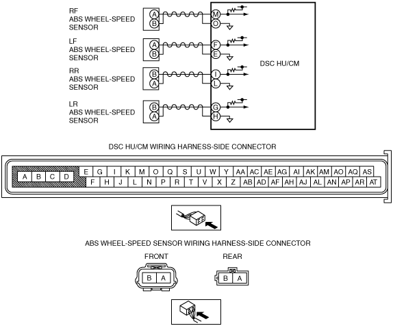
INSPECT FOR OPEN CIRCUIT IN WIRING HARNESS BETWEEN DSC HU/CM AND ABS WHEEL-SPEED SENSOR
• Turn the ignition switch to the LOCK position.
• Disconnect the DSC HU/CM connector and ABS wheel-speed sensor.
• Inspect for continuity in the wiring harness between the following ABS wheel-speed sensor connectors on the vehicle wiring harness-side and DSC HU/CM connectors.
-
― RF ABS wheel-speed sensor (+): M—A
― RF ABS wheel-speed sensor (–): O—B
― LF ABS wheel-speed sensor (+): F—A
― LF ABS wheel-speed sensor (–): E—B
― RR ABS wheel-speed sensor (+): I—B
― RR ABS wheel-speed sensor (–): L—A
― LR ABS wheel-speed sensor (+): G—B
― LR ABS wheel-speed sensor (–): H—A
• Is there continuity?
|
Yes
|
Go to the next step.
|
|
No
|
Repair or replace the wiring harness, then go to Step 5.
|
|
3
|
INSPECT WIRING HARNESS BETWEEN DSC HU/CM AND ABS WHEEL-SPEED SENSOR FOR SHORT TO POWER SUPPLY
• Inspect the voltage between the following terminals of the DSC HU/CM connector and body ground:
-
― RF ABS wheel-speed sensor (+): M—body ground
― RF ABS wheel-speed sensor (–): O—body ground
― LF ABS wheel-speed sensor (+): F—body ground
― LF ABS wheel-speed sensor (–): E—body ground
― RR ABS wheel-speed sensor (+): I—body ground
― RR ABS wheel-speed sensor (–): L—body ground
― LR ABS wheel-speed sensor (+): G—body ground
― LR ABS wheel-speed sensor (–): H—body ground
• Is the voltage approx. 0 V?
|
Yes
|
Go to the next step.
|
|
No
|
Repair or replace the wiring harness, then go to Step 5.
|
|
4
|
INSPECT FOR SHORT TO GROUND IN WIRING HARNESS BETWEEN DSC HU/CM AND ABS WHEEL-SPEED SENSOR
• Inspect for continuity in the wiring harness between the following DSC HU/CM connector terminals on the vehicle wiring harness-side and body ground.
-
― RF ABS wheel-speed sensor (+): M
― RF ABS wheel-speed sensor (–): O
― LF ABS wheel-speed sensor (+): F
― LF ABS wheel-speed sensor (–): E
― RR ABS wheel-speed sensor (+): I
― RR ABS wheel-speed sensor (–): L
― LR ABS wheel-speed sensor (+): G
― LR ABS wheel-speed sensor (–): H
• Is there continuity?
|
Yes
|
Repair or replace the wiring harness, then go to the next step.
|
|
No
|
Replace the ABS wheel-speed sensor, then go to the next step.
|
|
5
|
VERIFY THAT THE SAME DTC IS NOT PRESENT
• Make sure to reconnect all disconnected connectors.
• Clear the DTCs from the memory.
• Start the engine and drive the vehicle at 45 km/h {28 mph} or more.
• Are the same DTCs present?
|
Yes
|
Repeat the inspection from Step 1.
If the malfunction recurs, replace the DSC HU/CM, then go to the next step.
|
|
No
|
Go to the next step.
|
|
6
|
VERIFY THAT NO OTHER DTCS ARE PRESENT
• Are any other DTCs output?
|
Yes
|
Go to the applicable DTC inspection.
|
|
No
|
DTC troubleshooting completed.
|