 |
amxzzw00002230
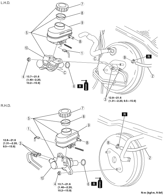
MASTER CYLINDER REMOVAL/INSTALLATION
id041100801300
1. Remove in the order indicated in the table.
2. Install in the reverse order of removal.
amxzzw00002230
|
|
1
|
Brake fluid level sensor connector
|
|
2
|
Hose (MT)
|
|
3
|
Brake pipe
|
|
4
|
Nut
|
|
5
|
Master cylinder
|
|
6
|
O-ring
|
|
7
|
Cap
|
|
8
|
Filter
|
|
9
|
Reserve tank
|
|
10
|
Cylinder component
|
Master Cylinder Installation Note
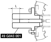
1. Install the SST to the power brake unit and tighten to the specified torque.
amxzzw00000245
|
2. Apply a vacuum of 66.7 kPa {500 mmHg, 19.7 inHg} to the power brake unit using a vacuum gauge.
amxzzw00000246
|
3. Using calipers, measure dimension L as shown in the figure.
amxzzw00000247
|
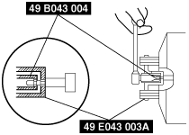
4. If dimension L is not within the standard, remove the SST (49 G043 001) and, while stopping the push rod rotation with the SST (49 E043 003A), adjust the push rod length with the SST (49 B043 004).
amxzzw00000248
|
5. Switch the SSTs and remeasure dimension L.
6. Install the master cylinder to the power brake unit.