 |
amxzzw00000260
FRONT ABS WHEEL-SPEED SENSOR INSPECTION
id041300801300
Installation Visual Inspection
1. Inspect the following items:
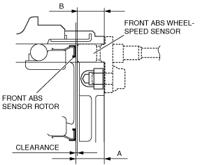
Clearance Inspection
1. Remove the front ABS wheel-speed sensor.
2. Measure the distance between the front ABS wheel-speed sensor installation surface and the front ABS sensor rotor. This is dimension A.
3. Measure the distance between the front ABS wheel-speed sensor installation surface and the tip of front ABS wheel-speed sensor. This is dimension B.
amxzzw00000260
|
4. Calculate the clearance between the front ABS wheel-speed sensor and the front ABS sensor rotor using the following formula:
5. Verify that the clearance between the front ABS sensor rotor and the front ABS wheel-speed sensor is as indicated below.
Sensor Output Value Inspection
1. Turn the ignition switch to the LOCK position.
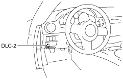
2. Connect the M-MDS to the DLC-2.
amxzzw00000129
|
3. Select the following PIDs using the M-MDS:
4. Start the engine and drive the vehicle.
5. Verify that the display of the M-MDS shows the same value as the speedometer.