 |
e5u740zw5010
MAGNETIC CLUTCH DISASSEMBLY/ASSEMBLY [FULL-AUTO AIR CONDITIONER]
id0740a1800400
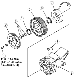
1. Disassemble in the order indicated in the table.
e5u740zw5010
|
|
1
|
Bolt
|
|
2
|
Pressure plate
|
|
3
|
Shim
(See Shim Installation Note.)
|
|
4
|
Snap ring
|
|
5
|
A/C compressor pulley
|
|
6
|
Snap ring
|
|
7
|
Stator
(See Stator Installation Note.)
|
|
8
|
Clamp
|
|
9
|
A/C compressor body
|
2. Assemble in the reverse order of disassembly.
3. Adjust the magnetic clutch clearance. (See MAGNETIC CLUTCH ADJUSTMENT [FULL-AUTO AIR CONDITIONER].)
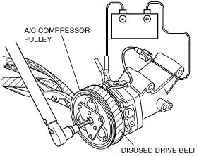
Bolt Removal/Installation Note
1. When removing or installing the bolt, lock the A/C compressor pulley against rotation using the following procedure.
amxuuw00001070
|
amxuuw00001071
|
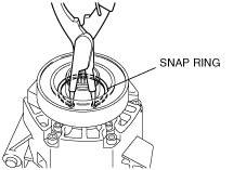
Snap Ring Removal/Installation Note
1. Remove the snap ring using a snap ring pliers.
e5u740zw5024
|
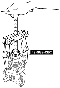
A/C Compressor Pulley Removal Note
1. Remove the A/C compressor pulley using the SST (49 0839 425C).
amxzzw00000974
|
e5u740zw5021
|
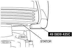
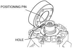
Stator Installation Note
1. Align the positioning pin with the hole of A/C compressor body and insert.
e5u740zw5025
|
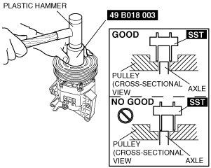
A/C Compressor Pulley Installation Note
1. Install the inner wheel of the pulley using a plastic hammer and SST (49 B018 003) to the compressor.
amxzzw00000691
|
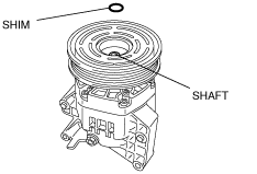
Shim Installation Note
1. First, insert the 1 mm (0.039 in) thick shim into the shaft.
e5u740zw5023
|