 |
amxzzw00001771
DTC B1318 [AIR BAG SYSTEM]
id0802a0810000
System Malfunction Location
|
DTC |
System Malfunction Location |
|---|---|
|
M-MDS display |
|
|
B1318
|
The power supply voltage decreases (less than 9v)
|
Detection Condition
Possible Causes
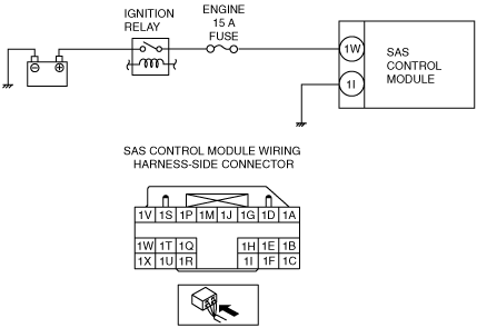
System Wiring Diagram
amxzzw00001771
|
Diagnostic Procedure
|
STEP |
INSPECTION |
ACTION |
|
|---|---|---|---|
|
1
|
BATTERY INSPECTION
• Refer to the battery inspection and inspect the battery.
(See BATTERY INSPECTION [L8, LF].)
• Is the battery normal?
|
Yes
|
Go to the next step.
|
|
No
|
Replace or charge the battery.
|
||
|
2
|
FUSE INSPECTION
• Turn the ignition switch to the LOCK position.
• Remove the battery cover.
• Disconnect the negative battery cable and wait for 1 min or more. (See BATTERY REMOVAL/INSTALLATION [L8, LF].)
• Remove the ENGINE 15 A fuse.
• Is the fuse normal?
|
Yes
|
Go to the next step.
|
|
No
|
Replace the ENGINE 15 A fuse.
|
||
|
3
|
INSPECT SAS CONTROL MODULE CONNECTOR
• Remove the console panel.
• Disconnect all SAS control module connectors.
• Inspect the SAS control module connection. (Corrosion, damage, and disconnected pins)
• Is there any malfunction of the SAS control module connector?
|
Yes
|
Replace the SAS control module wiring harness.
|
|
No
|
Go to the next step.
|
||
|
4
|
INSPECT WIRING HARNESS BETWEEN IGNITION RELAY AND SAS CONTROL MODULE
• Remove the column cover.
• Disconnect the clock spring connector.
• Remove the glove compartment.
• Disconnect the passenger-side air bag module connector. (See PASSENGER-SIDE AIR BAG MODULE REMOVAL/INSTALLATION.)
• Disconnect the driver and passenger-side seat connectors.
(See SEAT REMOVAL/INSTALLATION.)
• Remove the back trim.
• Remove the driver and passenger-side pre-tensioner seat belt connectors.
• Connect the negative battery cable.
• Turn the ignition switch to the ON position.
• Measure the voltage of SAS control module terminal 1W.
• Is the voltage between 9–16 V?
|
Yes
|
Go to the next step.
|
|
No
|
Replace the wiring harness between the ignition relay and SAS control module.
|
||
|
5
|
INSPECT WIRING HARNESS BETWEEN SAS CONTROL MODULE AND BODY GROUND
• Turn the ignition switch to the LOCK position.
• Disconnect the negative battery cable and wait 1 min or more.
• Inspect the wiring harness between SAS control module connector terminal 1I and body ground.
• Is the wiring harness normal?
|
Yes
|
Go to the next step.
|
|
No
|
Replace the wiring harness between the SAS control module and body ground.
|
||
|
6
|
PERFORM SAS CONTROL MODULE DTC INSPECTION
• Reconnect all disconnected connectors.
• Connect the negative battery cable.
• Turn the ignition switch to the ON position.
• Clear the DTC for the SAS control module using the M-MDS.
• Perform the DTC inspection for the SAS control module using the M-MDS.
• Are the same DTCs present?
|
Yes
|
Replace the SAS control module.
|
|
No
|
DTC troubleshooting completed.
|
||