DTC
Active bonnet warning light
System malfunction location
Memory function
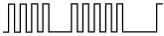
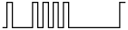
Flashing pattern
Order of precedence
B00D2:01
−
Continuously illuminated
1
Active bonnet warning light malfunction
X
B00D2:29
Active bonnet warning light communication error
X
B1001:11
19
11
Active bonnet actuator (RH) circuit short to ground
X
B1001:12
Active bonnet actuator (RH) circuit short to power supply
X
B1001:13
Active bonnet actuator (RH) circuit open circuit or resistance high
X
B1001:19
Short circuit in active bonnet actuator (RH) and (LH) circuits
X
B1001:1A
Active bonnet actuator (RH) circuit resistance low
X
B1003:11
21
10
Active bonnet actuator (LH) circuit short to ground
X
B1003:12
Active bonnet actuator (LH) circuit short to power supply
X
B1003:13
Active bonnet actuator (LH) circuit open circuit or resistance high
X
B1003:19
Short circuit in active bonnet actuator (LH) and (RH) circuits
X
B1003:1A
Active bonnet actuator (LH) circuit resistance low
X
B1011:95
58

5
Active bonnet control module connector partially disconnected
X
B1193:00
13
3
Recording of active bonnet control module collision data
X
B1422:11
44

6
Active bonnet sensor (right) circuit short to ground
X
B1422:13
Active bonnet sensor (right) circuit open circuit or short to body ground
X
B1422:87
No reception of active bonnet sensor (right) signal
X
B1422:55
Active bonnet control module internal malfunction
X
B1422:96
Active bonnet sensor (right) internal malfunction
X
B1423:11
43

7
Active bonnet sensor (right, center) circuit short to ground
X
B1423:13
Active bonnet sensor (right, center) circuit open circuit or short to power supply
X
B1423:87
No reception of active bonnet sensor (right, center) signal
X
B1423:55
Active bonnet control module internal malfunction
X
B1423:96
Active bonnet sensor (right, center) internal malfunction
X
B1424:11
46

8
Active bonnet sensor (left, center) circuit short to ground
X
B1424:13
Active bonnet sensor (left, center) circuit open circuit or short to power supply
X
B1424:87
No reception of active bonnet sensor (left, center) signal
X
B1424:55
Active bonnet control module internal malfunction
X
B1424:96
Active bonnet sensor (left, center) internal malfunction
X
B1425:11
45
9
Active bonnet sensor (left) circuit short to ground
X
B1425:13
Active bonnet sensor (left) circuit open circuit or short to power supply
X
B1425:87
No reception of active bonnet sensor (left) signal
X
B1425:55
Active bonnet control module internal malfunction
X
B1425:96
Active bonnet sensor (left) internal malfunction
X
U0001:88
14
4
CAN communication error
X
U0100:68
Communication error with PCM (vehicle speed signal)
X
U0155:00
Instrument cluster communication error
X
U3000:49
12
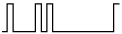
2
Active bonnet control module internal malfunction
X
U3003:16
−
Continuously illuminated
1
Active bonnet control module power supply voltage decrease (less than 8 V)
X
U3003:17
Active bonnet control module power supply voltage increase (18 V or more)
X