 |
amxzzw00000586
SECURITY LIGHT 11, DTC B1681/P1260 [IMMOBILIZER SYSTEM (KEYLESS ENTRY SYSTEM)]
id0902e5800600
|
DTC |
Security light flashing pattern |
11 |
No detected communication with coil antenna. |
|
|---|---|---|---|---|
|
M-MDS display |
Instrument cluster |
B1681 |
||
|
PCM |
P1260 |
|||
|
POSSIBLE CAUSE
|
• The coil antenna connector is pulled out
• Coil antenna malfunction
• Instrument cluster malfunction
• Related wiring harnesses malfunction
|
|||
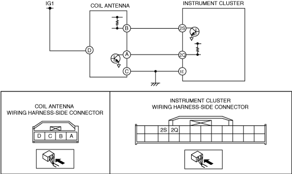
System wiring diagram
amxzzw00000586
|
Diagnostic Procedure
|
STEP |
INSPECTION |
ACTION |
|
|---|---|---|---|
|
1
|
INSPECT COIL ANTENNA POWER SUPPLY SYSTEM
• Disconnect the coil antenna connector.
• Turn the ignition switch to the ON position.
• Measure the voltage at coil antenna terminal D.
|
Yes
|
Go to the next step.
|
|
No
|
Repair the wiring harness.
|
||
|
2
|
INSPECT WIRING HARNESS BETWEEN COIL ANTENNA AND GROUND
• Turn the ignition switch to the LOCK position.
• Inspect the wiring harness between coil antenna terminal C and ground for the following:
• Is the wiring harness normal?
|
Yes
|
Go to the next step.
|
|
No
|
Repair the wiring harness.
|
||
|
3
|
INSPECT COIL ANTENNA INPUT SIGNAL CIRCUIT
• Connect the coil antenna connector.
• Turn the ignition switch to the ON position.
• Measure the voltage at coil antenna terminal B.
|
Yes
|
Go to Step 7.
|
|
No
|
Go to the next step.
|
||
|
4
|
INSPECT COIL ANTENNA INPUT SIGNAL CIRCUIT
• Turn the ignition switch to the LOCK position.
• Disconnect the instrument cluster connector.
• Turn the ignition switch to the ON position.
• Measure the voltage at instrument cluster terminal 2S.
|
Yes
|
Replace the instrument cluster and perform the resetting procedure for the immobilizer system when replacing the instrument cluster.
|
|
No
|
Go to the next step.
|
||
|
5
|
INSPECT COMMUNICATION CIRCUIT (INPUT) FOR CONTINUITY
• Turn the ignition switch to the LOCK position.
• Is there continuity between coil antenna terminal B and instrument cluster terminal 2S?
|
Yes
|
Go to the next step.
|
|
No
|
Repair the wiring harness.
|
||
|
6
|
INSPECT COIL ANTENNA INPUT SIGNAL CIRCUIT
• Measure the resistance between coil antenna terminal B and ground.
|
Yes
|
Replace the coil antenna.
|
|
No
|
Repair the wiring harness.
|
||
|
7
|
INSPECT COIL ANTENNA OUTPUT SIGNAL CIRCUIT
• Connect the coil antenna connector and the instrument cluster connector.
• Turn the ignition switch to the ON position.
• Measure the voltage at coil antenna terminal A.
|
Yes
|
Replace the coil antenna.
|
|
No
|
Go to the next step.
|
||
|
8
|
INSPECT COIL ANTENNA OUTPUT SIGNAL CIRCUIT
• Turn the ignition switch to the LOCK position.
• Disconnect the coil antenna connector.
• Turn the ignition switch to the ON position.
• Measure the voltage at coil antenna terminal A.
|
Yes
|
Replace the coil antenna.
|
|
No
|
Go to the next step.
|
||
|
9
|
INSPECT COMMUNICATION CIRCUIT (OUTPUT) FOR CONTINUITY
• Turn the ignition switch to the LOCK position.
• Disconnect the instrument cluster connector.
• Is there continuity between coil antenna terminal A and instrument cluster terminal 2Q?
|
Yes
|
Go to the next step.
|
|
No
|
Repair the wiring harness.
|
||
|
10
|
INSPECT COIL ANTENNA OUTPUT SIGNAL CIRCUIT
• Measure the resistance between instrument cluster terminal 2Q and ground.
|
Yes
|
Replace the instrument cluster and perform the resetting procedure for the immobilizer system when replacing the instrument cluster.
|
|
No
|
Repair the wiring harness.
|
||