 |
bsj7ja00000001
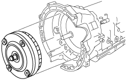
AUTOMATIC TRANSMISSION DISASSEMBLY
id051300260100
Precaution
1. Handle electronic parts with care
2. Prevent foreign matter from penetrating
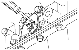
3. Prevent scratching
4. Prevent incorrect or insufficient, installation or missing parts
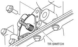
5. Wash parts and apply oil
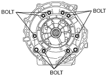
6. ATF care
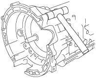
Disassembly
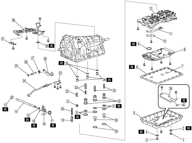
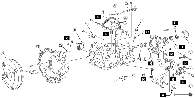
Components
bsj7ja00000001
|
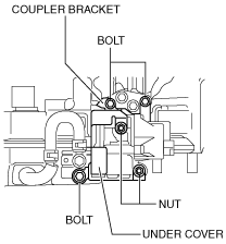
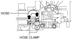
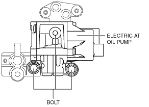
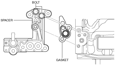
|
1
|
Extension dust deflector
|
|
2
|
Extension housing shroud
|
|
3
|
Oil seal
|
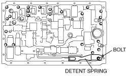
|
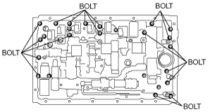
4
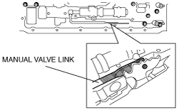
|
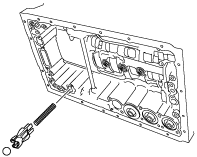
Under cover (with i-stop)
|
|
5
|
Coupler bracket (with i-stop)
|
|
6
|
Hose (with i-stop)
|
|
7
|
Electric AT oil pump (with i-stop)
|
|
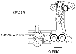
8
|
Spacer (with i-stop)
|
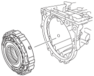
|
9
|
Gasket (with i-stop)
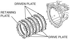
|
|
10
|
Elbow (with i-stop)
|
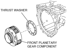
|
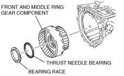
11
|
O-ring (with i-stop)
|
|
12
|
Extension housing
|
|
13
|
Oil seal (with i-stop)
|
|
14
|
Snap ring (MX-5 (ND))
|
|
15
|
Bearing (MX-5 (ND))
|
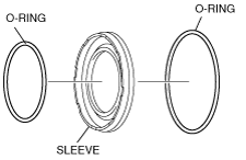
|
16
|
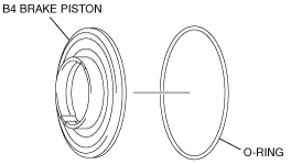
Filler plug
|
|
17
|
O-ring
|
|
18
|
Check plug
|
|
19
|
O-ring
|
|
20
|
VSS
|
|
21
|
Breather hose
|
|
22
|
Breather tube
|
|
23
|
Oil pipe (MX-5 (ND))
|
|
24
|
Bracket (MX-5 (ND))
|
|
25
|
Turbine sensor
|
|
26
|
TR switch
|
|
27
|
Torque converter
|
|
28
|
Converter housing
|
|
29
|
Breather pipe
|
bsj7ja00000002
|
|
1
|
Drain plug
|
|
2
|
Gasket
|
|
3
|
Overflow plug
|
|
4
|
Gasket
|
|
5
|
Oil pan
|
|
6
|
Oil pan gasket
|
|
7
|
Magnet
|
|
8
|
Oil strainer
|
|
9
|
O-ring
|
|
10
|
Detent spring cover
|
|
11
|
Detent spring
|
|
12
|
Control valve body
|
|
13
|
Oil seal
|
|
14
|
Manual shaft
|
|
15
|
Manual shaft washer
|
|
16
|
Pin
|
|
17
|
Oil seal
|
|
18
|
Manual valve
|
|
19
|
Check valve
|
|
20
|
Spring
|
|
21
|
Accumulator piston
|
|
22
|
Spring
|
|
23
|
Bracket
|
|
24
|
Parking rod
|
|
25
|
Driven plate
|
|
26
|
Shaft parking pawl
|
|
27
|
Spring
|
|
28
|
Parking pawl
|
|
29
|
Snap ring
|
|
30
|
Spring
|
|
31
|
O-ring
|
|
32
|
Accumulator piston
|
|
33
|
Accumulator spring
|
|
34
|
Gasket
|
|
35
|
Gasket
|
|
36
|
O-ring
|
|
37
|
Clip
|
|
38
|
Coupler component
|
|
39
|
Oil strainer (electric AT oil pump) (with i-stop)
|
|
40
|
O-ring (with i-stop)
|
bsj6za00000735
|
|
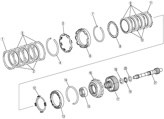
1
|
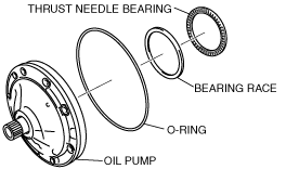
Oil pump
|
|
2
|
O-ring
|
|
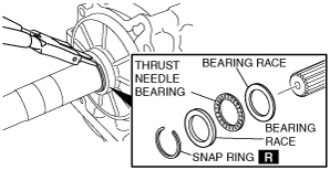
3
|
Bearing race
|
|
4
|
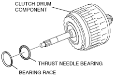
Thrust needle bearing
|
|
5
|
Bearing race
|
|
6
|
Thrust needle bearing
|
|
7
|
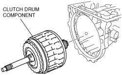
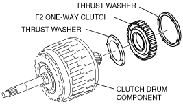
Clutch drum component
|
|
8
|
Thrust washer
|
|
9
|
F2 one-way clutch
|
|
10
|
Thrust washer
|
|
11
|
Snap ring
|
|
12
|
Driven plate
|
|
13
|
Drive plate
|
|
14
|
Snap ring
|
|
15
|
B3 brake piston component
|
|
16
|
F1 one-way clutch
|
|
17
|
Thrust washer
|
|
18
|
Bearing race
|
|
19
|
Front planetary gear component
|
|
20
|
Thrust washer
|
|
21
|
Bearing race
|
|
22
|
Thrust needle bearing
|
|
23
|
Front and middle ring gear component
|
|
24
|
Thrust needle bearing
|
|
25
|
Bearing race
|
|
26
|
Front planetary gear component
|
|
27
|
Sun gear
|
bsj6za00000736
|
|
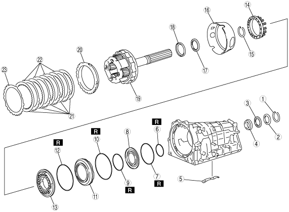
1
|
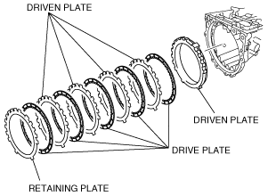
Retaining plate
|
|
2
|
Driven plate component
|
|
3
|
Driven plate
|
|
4
|
Snap ring
|
|
5
|
Pinion return spring
|
|
6
|
B1 brake piston component
|
|
7
|
Snap ring
|
|
8
|
Retaining plate
|
|
9
|
Drive plate
|
|
10
|
Driven plate
|
|
11
|
Driven plate
|
|
12
|
Piston return spring
|
|
13
|
B2 brake piston component
|
|
14
|
Snap ring
|
|
15
|
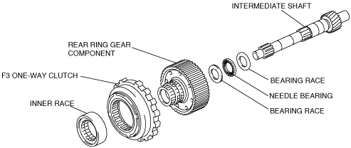
Inner race
|
|
16
|
F3 one-way clutch
|
|
17
|
Rear ring gear component
|
|
18
|
Bearing race
|
|
19
|
Needle bearing
|
|
20
|
Bearing race
|
|
21
|
Intermediate shaft
|
bsj6za00000737
|
|
1
|
Snap ring
|
|
2
|
Bearing race
|
|
3
|
Thrust needle bearing
|
|
4
|
Bearing race
|
|
5
|
Stopper spring
|
|
6
|
O-ring
|
|
7
|
O-ring
|
|
8
|
Inner brake piston
|
|
9
|
O-ring
|
|
10
|
O-ring
|
|
11
|
Sleeve
|
|
12
|
O-ring
|
|
13
|
B4 brake piston
|
|
14
|
Piston return spring
|
|
15
|
Snap ring
|
|
16
|
Brake tube
|
|
17
|
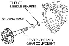
Thrust needle bearing
|
|
18
|
Bearing race
|
|
19
|
Rear planetary gear component
|
|
20
|
O-ring
|
|
21
|
Inner brake piston
|
|
22
|
O-ring
|
|
23
|
O-ring
|
Disassembly procedure
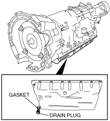
1. Remove the drain plug and gasket.
bsj6za00000738
|
2. Remove the torque converter.
bsj6za00000393
|
3. Remove the breather hose, breather tube and breather pipe.
bsj8ua00000002
|
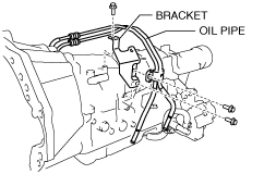
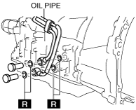
4. Remove the oil pipe and bracket. (MX-5 (ND))
LH
bsj8ua00000003
|
RH
bsj8ua00000004
|
5. Remove the turbine sensor.
bsj6za00000740
|
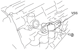
6. Remove the VSS.
bsj6za00000741
|
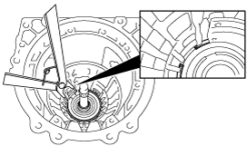
7. Lift up the lock washer using a flathead screwdriver.
bsj6za00000854
|
8. Remove the nut and lock washer.
bsj6za00000023
|
9. Remove the TR switch.
bsj6za00000742
|
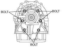
10. Remove the bolts as shown in the figure.
bsj6za00000816
|
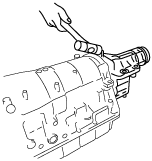
11. Using a plastic hammer, tap the converter housing to remove it.
bsj6za00000372
|
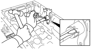
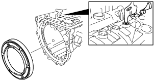
12. Using a plastic hammer and slab of wood, tap the extension dust deflector to remove it.
bsj6za00000614
|
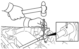
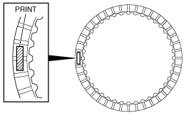
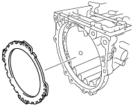
13. Using a flathead screwdriver, remove the extension housing shroud.
bsj6za00000615
|
14. Using a flathead screwdriver, remove the oil seal.
bsj6za00000616
|
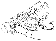
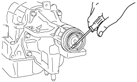
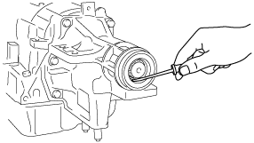
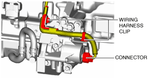
15. Remove the electric AT oil pump. (with i-stop)
amxzzw00003295
|
amxzzw00003296
|
amxzzw00003297
|
amxzzw00003298
|
amxzzw00003299
|
amxzzw00003300
|
16. Remove the bolts as shown in the figure.
MX-5 (ND)
bsj8ua00000005
|
MX-5 (NC), RX-8 (SE)
bsj6za00000817
|
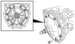
17. Using a plastic hammer, tap the extension housing to remove it.
bsj6za00000588
|
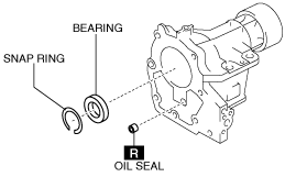
18. Remove the snap ring, bearing, and oil seal. (MX-5 (ND))
bsj6za00000899
|
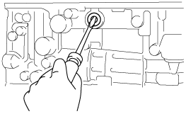
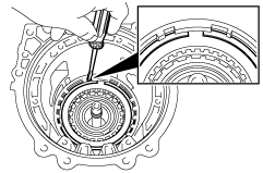
19. Remove the snap ring using snap ring pliers.
bsj6za00000743
|
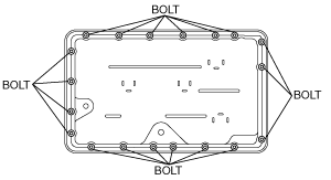
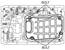
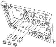
20. Remove the bolt as shown in the figure and remove the oil pan and gasket.
bsj6za00000744
|
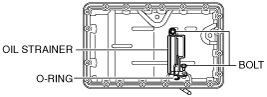
21. Remove the oil strainer (electric AT oil pump) and O-ring. (with i-stop)
amxzzw00003309
|
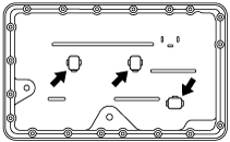
22. Remove the magnet from the oil pan.
bsj6za00000900
|
23. Remove the oil strainer from the control valve body component.
bsj6za00000745
|
24. Remove the O-ring from the oil strainer.
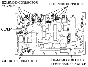
25. Disconnect the solenoid connectors from the solenoids.
bsj6za00000746
|
26. Disconnect the coupler component from the clamps.
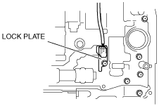
27. Remove the lock plate from the control valve body component.
bsj6za00000747
|
28. Disconnect the transmission fluid temperature switch from the control valve body component.
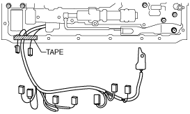
29. Fix the coupler component with tape to the transmission case as shown in the figure.
bsj6za00000748
|
30. Disconnect the detent spring cover and detent spring from the control valve body component.
bsj6za00000749
|
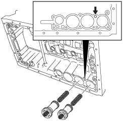
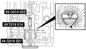
31. Remove the bolts from transmission case.
bsj6za00000824
|
32. Disconnect the manual valve link and remove the control valve body component.
bsj6za00000750
|
33. Remove the check valve subcomponent and compression spring from transmission case.
bsj6za00000825
|
34. Remove the transmission case gasket and brake drum gasket from transmission case.
bsj6za00000039
|
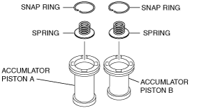
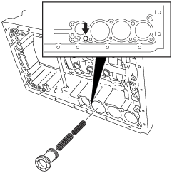
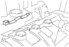
35. Blow compressed air from the oil passage shown in the figure and remove accumulator pistons A and B and the compression spring from the transmission case.
bsj6za00000040
|
36. Using a flathead screwdriver, remove the snap ring from accumulator pistons A and B.
bsj6za00000751
|
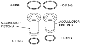
37. Remove the compression spring from accumulator piston A and B.
38. Using a flathead screwdriver, remove the O-ring from accumulator piston A and B.
bsj6za00000752
|
39. Blow compressed air from the oil passage shown in the figure and remove accumulator pistons C and the compression springs from the transmission case.
bsj6za00000041
|
40. Using a flathead screwdriver, remove the O-ring from accumulator pistons C.
41. Remove the accumulator valve and compression springs from the transmission case.
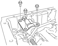
42. Remove the bracket.
bsj6za00000441
|
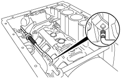
43. Remove the parking rod from the manual valve lever.
bsj6za00000442
|
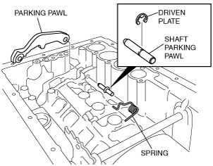
44. Pull out the shaft parking pawl and spring.
bsj6za00000753
|
45. Using a flathead screwdriver, remove the driven plate from shaft parking pawl.
46. Remove the parking pawl.
47. Using a flathead screwdriver and hammer, remove the manual shaft washer.
bsj6za00000444
|
48. Using a hammer and pin punch, remove the pin.
bsj6za00000445
|
49. Pull out the manual shaft and remove the manual valve component.
bsj6za00000754
|
50. Using a flathead screwdriver, remove the oil seal.
bsj6za00000447
|
51. Remove the bolts from the oil pump as shown in the figure.
bsj6za00000448
|
52. Using a flathead screwdriver, remove the oil pump.
bsj6za00000550
|
53. Remove the O-ring from the oil pump.
bsj6za00000755
|
54. Remove the thrust needle bearing and bearing race from oil pump.
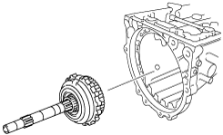
55. Remove the clutch drum component.
bsj6za00000756
|
56. Remove the thrust needle bearing and bearing race from the clutch drum component.
bsj6za00000757
|
57. Remove the thrust washer and F2 one-way clutch component from the clutch drum component.
bsj6za00000758
|
58. Using a flathead screwdriver, remove the snap ring from the transmission case component.
bsj6za00000407
|
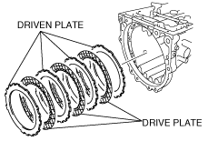
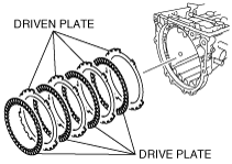
59. Remove the retaining plates, drive and driven plates.
bsj6za00000759
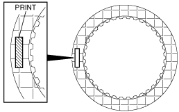
|
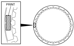
60. Inspect the lining of all drive plates.
bsj6za00000760
|
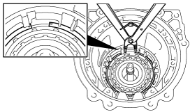
61. Remove the snap ring from transmission case using snap ring pliers.
bsj6za00000463
|
62. Remove the B2 brake piston component and F1 one-way clutch.
bsj6za00000464
|
63. Remove the bearing race and thrust washer from the F1 one-way clutch component.
bsj6za00000761
|
64. Remove the F1 one-way clutch component from the B3 brake piston component.
65. Remove the front planetary gear component and thrust washer.
bsj6za00000762
|
66. Remove the front and middle ring gear component.
bsj6za00000763
|
67. Remove the bearing race and thrust needle bearing from front and middle ring gear component.
68. Remove the retaining plates, drive and driven plates.
bsj6za00000764
|
69. Inspect the lining of all drive plates.
bsj6za00000765
|
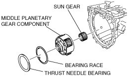
70. Remove the middle planetary gear component and sun gear.
bsj6za00000766
|
71. Remove the bearing race and thrust needle bearing from middle planetary gear component.
72. Using a flathead screwdriver, remove the snap ring from transmission case component.
bsj6za00000469
|
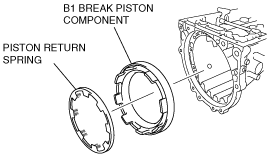
73. Remove the piston return spring and B1brake piston component.
bsj6za00000767
|
74. Using a flathead screwdriver, remove the snap ring from transmission case.
bsj6za00000471
|
75. Remove the driven plate.
bsj6za00000472
|
76. Remove the retaining plates, drive and driven plates.
bsj6za00000768
|
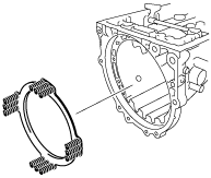
77. Remove the piston return spring.
bsj6za00000423
|
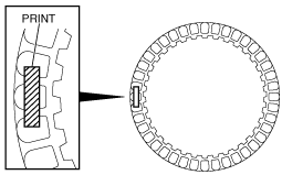
78. Inspect the lining of all drive plates
bsj6za00000769
|
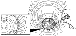
79. Blow compressed air into the oil passage as shown in the figure while pressing the B2 brake piston component by hand and remove the B2 brake piston component from the transmission case.
bsj6za00000425
|
80. Remove the stopper spring from the transmission case.
bsj6za00000426
|
81. Remove the snap ring from the transmission case using snap ring pliers.
bsj6za00000427
|
82. Remove the following parts from the transmission case and disassemble in the order indicated below.
bsj6za00000428
|
bsj6za00000770
|
83. Remove the retaining plates, drive and driven plates.
bsj6za00000771
|
84. Inspect the lining of all drive plates.
bsj6za00000772
|
85. Remove the rear planetary gear component and bearing race and thrust needle bearing.
bsj6za00000773
|
86. Remove the brake tube.
bsj6za00000433
|
87. Compress the piston return spring using the SSTs and remove the snap ring.
bsj6za00000596
|
88. Remove the piston return spring.
bsj6za00000453
|
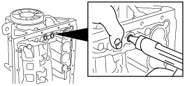
89. Blow compressed air into the oil passage as shown in the figure while pressing the B4 brake piston component by hand and remove the B4 brake piston component from the transmission case.
bsj6za00000477
|
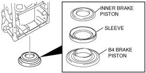
90. Remove the inner brake piston and sleeve and B4 brake piston.
bsj6za00000774
|
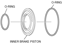
91. Remove the O-ring from the inner brake piston.
bsj6za00000775
|
92. Remove the O-ring from sleeve.
bsj6za00000776
|
93. Remove the O-ring from B4 brake piston.
bsj6za00000777
|