 |
bmm8um00000047
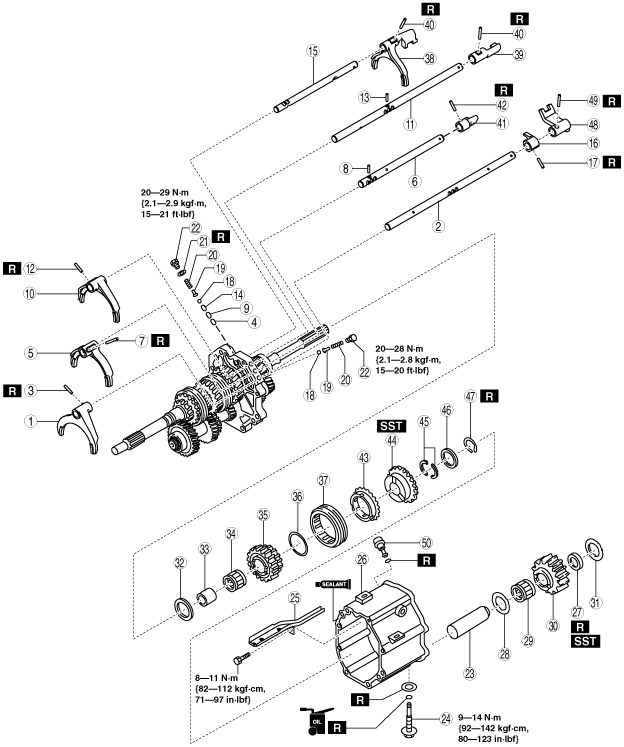
SHIFT FORK, SHIFT ROD AND REVERSE GEAR PARTS ASSEMBLY
id051100010500
1. Assemble in the order shown in the figure.
bmm8um00000047
|
|
1
|
5th/6th shift fork
|
|
2
|
5th/6th shift rod
(See Shift Rod Assembly Note.)
|
|
3
|
Roll pin
(See Roll Pin Assembly Note.)
|
|
4
|
Interlock pin (short)
|
|
5
|
3rd/4th shift fork
|
|
6
|
3rd/4th shift rod
(See Shift Rod Assembly Note.)
|
|
7
|
Roll pin
(See Roll Pin Assembly Note.)
|
|
8
|
Interlock pin (long)
|
|
9
|
Interlock pin (short)
|
|
10
|
1st/2nd shift fork
|
|
11
|
1st/2nd shift rod
(See Shift Rod Assembly Note.)
|
|
12
|
Roll pin
(See Roll Pin Assembly Note.)
|
|
13
|
Interlock pin (long)
|
|
14
|
Interlock pin (short)
|
|
15
|
Reverse shift rod
(See Shift Rod Assembly Note.)
|
|
16
|
Stopper block
|
|
17
|
Roll pin
(See Roll Pin Assembly Note.)
|
|
18
|
Detent ball
|
|
19
|
Spring seat
|
|
20
|
Spring
|
|
21
|
Washer
|
|
22
|
Cap plug
|
|
23
|
Reverse idle gear shaft
|
|
24
|
Idle shaft pin
(See Idle Shaft Pin Assembly Note.)
|
|
25
|
Oil guide
|
|
26
|
Intermediate housing
|
|
27
|
Friction damper
|
|
28
|
Washer
|
|
29
|
Bearing
|
|
30
|
Reverse idle gear
|
|
31
|
Washer
|
|
32
|
Washer
|
|
33
|
Bearing race
|
|
34
|
Bearing
|
|
35
|
Reverse gear
|
|
36
|
Reverse synchronizer key spring
|
|
37
|
Reverse clutch hub sleeve
|
|
38
|
Reverse shift fork
|
|
39
|
1st/2nd shift rod end
|
|
40
|
Roll pin
(See Roll Pin Assembly Note.)
|
|
41
|
3rd/4th shift rod end
|
|
42
|
Roll pin
(See Roll Pin Assembly Note.)
|
|
43
|
Reverse synchronizer ring
|
|
44
|
Reverse synchronizer cone
|
|
45
|
C-washer
(See C-washer Assembly Note.)
|
|
46
|
Washer
|
|
47
|
Snap ring
|
|
48
|
5th/6th shift rod end
|
|
49
|
Roll pin
(See Roll Pin Assembly Note.)
|
|
50
|
Breather
|
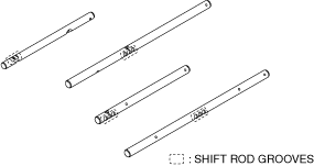
Shift Rod Assembly Note
1. Assemble the shift rods to the bearing housing with the shift rod grooves shown in the figure pointed towards the shift check mechanism side.
bmm7zm00000003
|
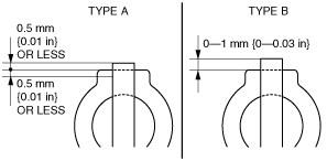
Roll Pin Assembly Note
1. Assemble the new roll pins using a pin punch and a hammer.
bmm8um00000012
|
|
Roll pin location of use |
Tap-in amount type |
|---|---|
|
5th/6th shift fork
|
Type A
|
|
1st/2nd shift fork
|
Type A
|
|
3rd/4th shift fork
|
Type A
|
|
Stopper block
|
Type A
|
|
1st/2nd shift rod end
|
Type B
|
|
3rd/4th shift rod end
|
Type B
|
|
5th/6th shift rod end
|
Type B
|
|
Reverse shift fork
|
Type B
|
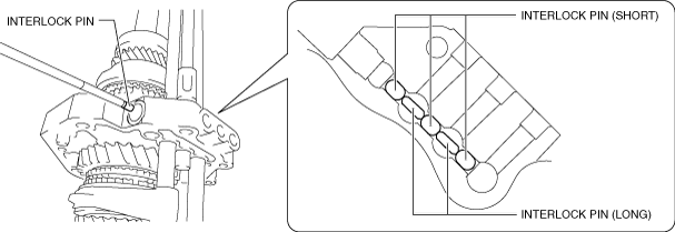
Interlock Pin (Short)/(Long) Assembly Note
1. Assemble the interlock pins (short)/(long) to the positions on the bearing housing shown in the figure using a magnet.
bmm7zm00000004
|
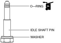
Idle Shaft Pin Assembly Note
1. Assemble the new O-ring to the end of the idle shaft pin, and apply transmission oil (long-life gear oil IS).
bmm8um00000014
|
2. Assemble the idle shaft pin through the new washer.
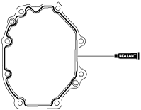
Intermediate Housing Assembly Note
1. Apply silicone sealant TB1217E to the intermediate housing as shown in the figure.
bmm6jm00000058
|
2. Assemble the intermediate housing.
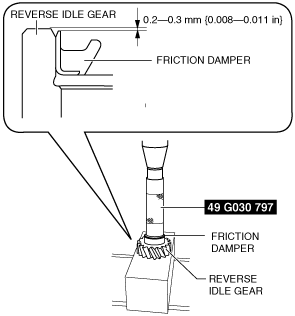
Friction Damper Assembly Note
1. Assemble the new friction damper to the reverse idle gear using the SST and the press.
bmm8um00000015
|
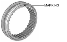
Reverse Clutch Hub Sleeve Assembly Note
1. Assemble so that the reverse clutch hub sleeve marking is pointing toward the extension housing side.
bmm8um00000016
|
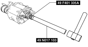
Reverse Synchronizer Cone Assembly Note
1. Assemble the reverse synchronizer cone using the SSTs and a hammer.
bmm6jm00000061
|
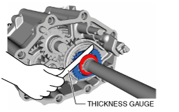
C-washer Assembly Note
1. Assemble the removed C-washer during disassembly to the washer, and assemble the snap ring.
2. Measure the clearance between the reverse synchronizer cone and C-washer with a thickness gauge.
bmm8um00000017
|
|
C-washer thickness (mm {in}) |
|---|
|
3.1 {0.123}
|
|
3.2 {0.126}
|
|
3.3 {0.130}
|
|
3.4 {0.134}
|
3. Assemble the adjusted C-washer to the washer and assemble the new snap ring.