AIM OF DEVELOPMENT
id000000100100
Product Concept
• “Joy of the Moment, Joy of Life”
Appealing to the senses and sensations through which people enjoy cars.
Vehicle Outline
Design
-
• A design that sets anybody’s heart pounding with excitement.
-
― Beautiful proportions that make the occupants stand out and look good.
― A deeper expression of the KODO design language that conveys agility.
― Body surfaces that richly express the Japanese sense of contrast between stillness and motion.
― An interior design that melts away the boundaries between the inside and outside of the car.
― A snug feeling cockpit with symmetry and a singular axis that enables concentration on driving.
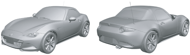
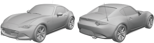
Exterior design
Convertible Top
Retractable Hardtop
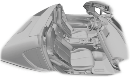
Interior design
Convertible Top
Retractable Hardtop
Engine
-
• SKYACTIV-G 1.5 and SKYACTIV-G 2.0 have been adopted.
-
Engine mechanical
-
• For SKYACTIV-G 1.5 and SKYACTIV-G 2.0 are the following has been implemented to lower fuel consumption.
-
― Sliding resistance*1 reduction
-
• Rocker arm (with built-in needle roller bearing) adopted for cam-contact area
• Reduced valve spring load
• Narrowed down crankshaft journal
• Optimized piston skirt shape
• Lowered piston ring tension
• Lowered drive belt tension
• Suppressed chain tensioner load by stabilized timing chain behavior
• Oil shower pipe adopted
― Mechanical resistance loss reduction
-
• Optimized oil passage
• Optimized oil pump shape
• Engine oil control adopted
― Cooling loss reduction in early stage of combustion
-
• Piston cavity adopted
― Pumping loss*2 reduction
-
• Variable valve timing mechanism adopted on both intake and exhaust sides for fine control of exhaust amount and internal EGR volume
― Cooling efficiency improvement
-
• Air seal cowl adopted
• Optimized cooling fan shape
• Optimized engine coolant passage
• Optimized water pump impeller shape
― Combustion efficiency improvement
-
• Multiple hole-type fuel injectors adopted
• High-pressure fuel pump adopted
-
• The HLA has been adopted to achieve the maintenance-free valve clearance.
• The 4-2-1 type exhaust pipes have been adopted for the exhaust manifold to achieve an engine with a high compression ratio.
• L-jetronic*3 and D-jetronic*4 types have been adopted for the intake air amount measurement to achieve stable combustion free from abnormal combustion.
-
― MAF sensor adopted
― MAP sensor adopted
― IAT sensor No.1 and No.2 adopted
-
• To improve the fuel economy and emission performance, an electric variable valve timing control has been adopted for the intake side, and a hydraulic variable valve timing control for the exhaust side. The electric type is adopted for the intake side to achieve expanded valve overlap and delayed closing of the intake valve (enlarged intake valve opening angle).
Intake side: Electric variable valve timing control
-
― Intake CMP sensor adopted
― Electric variable valve timing motor/driver adopted
― Electric variable valve timing relay adopted
Exhaust side: Hydraulic variable valve timing control
-
― Exhaust CMP sensor adopted
-
• Engine hydraulic pressure switching control has been adopted to reduce the oil pump operation load on the engine.
-
― Engine oil solenoid valve adopted
-
• To decrease generator operation loss, i-ELOOP has been adopted which generates electricity from energy occurring when the vehicle decelerates. (With i-ELOOP)
-
― DC-DC converter (i-ELOOP) adopted
-
• Generator output control has been adopted to improve fuel economy/idling stability.
-
― A current sensor adopted (With i-stop system)
-
• To improve engine reliability, an ion sensor has been adopted which detects pre-ignition.
• LIN communication has been adopted to the current sensor to realize wiring harness simplification. (With i-stop system)
• i-stop control has been adopted to improve fuel efficiency, and reduce exhaust gas and idling noise. (With i-stop system)
*1 :Resistance (friction force) which occurs when objects slide. The larger the sliding resistance, the greater the energy loss.
*2 :Energy loss due to resistance in each part during intake/exhaust process is called pumping loss.
*3 :The intake air amount is directly detected by measuring the amount of intake air flow using the MAF sensor.
*4 :The intake air amount is detected indirectly by measuring the intake manifold pressure (pressure between downstream of the throttle valve and intake manifold) using the MAP sensor.
-
Engine control
-
• L-jetronic*1 and D-jetronic*2 types have been adopted for the intake air amount measurement to realize stable combustion free from abnormal combustion.
-
― MAF sensor adopted
― MAP sensor adopted
― IAT sensor No.1 and No.2 adopted
-
• To improve the fuel economy and emission performance, an electric variable valve timing control has been adopted for the intake side, and a hydraulic variable valve timing control for the exhaust side. The electric type is adopted for the intake side to achieve expanded valve overlap and delayed closing of the intake valve (enlarged intake valve opening angle).
Intake side: Electric variable valve timing control
-
― Intake CMP sensor adopted
― Electric variable valve timing motor/driver adopted
― Electric variable valve timing relay adopted
Exhaust side: Hydraulic variable valve timing control
-
― Exhaust CMP sensor adopted
-
• Engine hydraulic pressure switching control has been adopted to reduce the oil pump operation load on the engine.
-
― Engine oil solenoid valve adopted
-
• To decrease generator operation loss, i-ELOOP has been adopted which generates electricity from energy occurring when the vehicle decelerates. (With i-ELOOP)
-
― DC-DC converter (i-ELOOP) adopted
-
• Generator output control has been adopted to improve fuel economy/idling stability.
-
― A current sensor adopted (With i-stop system)
-
• To improve engine reliability, an ion sensor has been adopted which detects pre-ignition.
• LIN communication has been adopted to the current sensor to realize wiring harness simplification. (With i-stop system)
• i-stop control has been adopted to improve fuel efficiency, and reduce exhaust gas and idling noise. (With i-stop system)
*1 :The intake air amount is directly detected by measuring the amount of intake air flow using the MAF sensor.
*2 :The intake air amount is detected indirectly by measuring the intake manifold pressure (pressure between downstream of the throttle valve and intake manifold) using the MAP sensor.
Suspension
-
• Front suspension
-
― An in-wheel-type double-wishbone suspension has been adopted.
― The front crossmember under cover is made of aluminum. In addition, by eliminating the transverse member and having the front crossmember under cover function as the transverse member, the front suspension achieves both weight reduction and superior rigidity.
― The amount of the camber angle variation has been increased due to the optimized caster angle of the front suspension. As the result, the handling performance has been improved.
― The negative king pin offset improves braking stability during evasive maneuvering or cornering.
-
• Negative king pin offset: The virtual king pin axis contact point is located on the outer side of the tire/wheel centerline contact point.
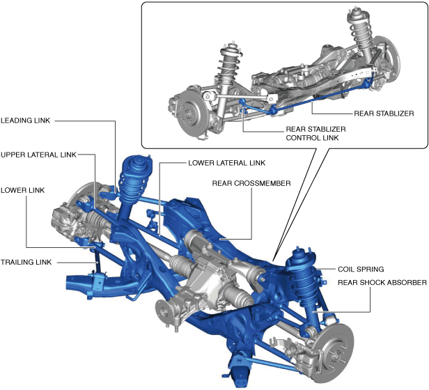
• Rear suspension
-
― A multi-link suspension composed of five links has been adopted.
― The rigidity has been improved by changing the rear crossmember to a deform-resistant truss shape.
― The suspension system layout is such that the virtual rear wheel hub center axis contact point is forward of the virtual king pin contact point. Due to this, lateral force on the rear wheels during toe-in is optimized when cornering. In particular, when exiting a corner the shock absorber provides an assured, high level of gripping power.
― By setting the shock absorber input point closer to the wheel center, the damper lever ratio is optimized, improving traction while cornering.
Driveline/Axle
-
• Double angular ball bearings which integrated the wheel hub and the wheel bearing have been adopted for the front and rear axles.
• An aluminum front knuckle and rear knuckle have been adopted, and unsprung weight has been reduced.
• An aluminum differential carrier and differential rear cover have been adopted, reducing rear differential weight.
• A super-LSD has been adopted (limited slip differential (LSD) vehicles).
• The following parts have been adopted to reduce vibration and noise:
-
― Bell-shaped constant velocity joint has been adopted for the wheel-side joint of the rear drive shaft.
― A tripod-shaped constant velocity joint has been adopted for the differential-side joint of the rear drive shaft.
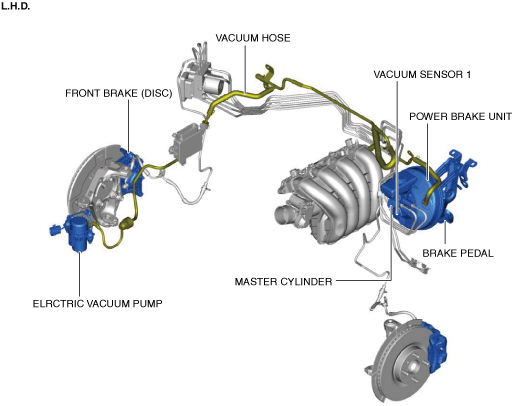
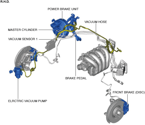
Brakes
-
• Conventional brake system
-
― A brake pedal with an intrusion minimizing mechanism has been adopted. As a result, driver safety has been improved.
― A plunger-type master cylinder has been adopted, improving durability and response.
― A electric vacuum pump has been adopted, improving braking force.
― For the front brake (disc), a ventilated-type disc brake has been adopted.
― For the rear brake (disc), a solid-type disc brake has been adopted.
Vehicle front side
Vehicle rear side
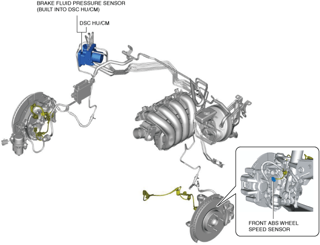
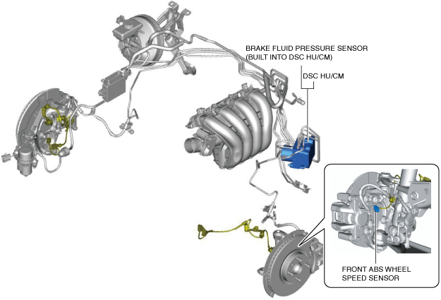
• Dynamic stability control
-
― Electrical brake assist control has been adopted, improving safety.
― The DSC HU/CM, integrating both the Hydraulic Unit (HU) and Control Module (CM), has been adopted, resulting in a size and weight reduction.
― An enhanced malfunction diagnosis system, used with the Mazda Modular Diagnostic System (M-MDS), has been adopted, improving serviceability.
― Serviceability improved by the automatic configuration function.
― The vehicle roll prevention function, Hill Launch Assist (HLA) have been adopted, improving safety.
Vehicle front side (L.H.D.)
Vehicle front side (R.H.D.)
Vehicle rear side
Transaxle/Transmission
-
• Manual transmission (M66M-D)
-
― Six-speed M66M-D manual transmission has been adopted.
-
• Automatic transmission (SJ6A-EL)
-
― Six-speed SJ6A-EL automatic transmission has been adopted.
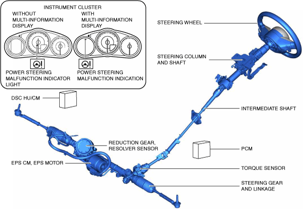
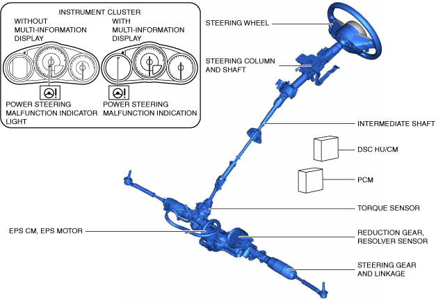
Steering
-
• Power steering
-
― A pinion-assist type Electric Power Steering (EPS) has been adopted.
― EPS provides smooth handling from low to high speeds as a result of the excellent steering feel provided by the electronic control and the vehicle-speed responsive control.
― EPS does not require a power steering oil pump and generates assist force only when the steering wheel is steered. As a result, engine load is lowered and fuel efficiency is improved.
― A high output efficiency motor has been adopted, improving responsiveness to steering operation.
― The EPS Control Module (CM) has been integrated with the EPS motor, resulting in a size and weight reduction.
― Serviceability improved by the automatic configuration function and the steering wheel angle neutral position auto-learning function.
L.H.D.
R.H.D.
Heater, ventilation and air conditioning
-
• An A/C unit and air dist unit have been adopted to the blower system.
• A refrigerant pressure sensor has been adopted in which refrigerant pressure is converted to a linear electrical signal and precise information is transmitted.
Restraints
-
• The following have been adopted to the air bag modules and seat belts.
×: Applicable
—: Not applicable
|
Seat position
|
Air bag module
|
Seat belt
|
|
Driver-side air bag module
|
Passenger-side air bag module
|
Side air bag module
|
ELR (Emergency Locking Retractor)
|
Load limiter
|
Pre-tensioner seat belt
|
|
Driver's seat
|
×
|
—
|
×
|
×
|
×
|
×
|
|
Passenger's seat
|
—
|
×
|
×
|
×
|
×
|
×
|
i-ACTIVSENSE
-
Active safety technology
-
• The following systems have been adopted.
|
System
|
Outline
|
Reference
|
|
High Beam Control (HBC) System
|
The High Beam Control (HBC) system turns the headlights HI off when the forward sensing camera (FSC) installed to the windshield recognizes a vehicle ahead and when traveling through towns and cities while the vehicle is being driven with the headlights HI turned on. Due to this, blinding of other vehicles from headlight glare is prevented and driver visibility is assured.
|
|
|
Lane departure warning system (LDWS)
|
The Lane Departure Warning System (LDWS) recognizes vehicle lane lines on a road using the forward sensing camera (FSC) installed to the windshield, and if the vehicle departs from its lane unbeknownst to the driver, the system alerts the driver of the lane departure using a warning indication and warning sound.
|
|
|
Adaptive LED headlights
|
The adaptive LED headlights improve visibility by changing the headlight illumination range depending on the vehicle driving conditions and the surrounding conditions without switching the headlights between HI/LO.
|
|
|
Adaptive front lighting system (AFS)
|
The adaptive front lighting system (AFS) is a system which enhances the range of visibility when the headlights are turned on by pointing the optical axis of the headlights in the direction in which the steering wheel is operated according to the steering operation.
|
|
|
Blind spot monitoring (BSM) system
|
The blind spot monitoring (BSM) system detects a vehicle in the blind-spot area at the rear of the vehicle to alert the driver of the possible collision with a target vehicle using the blind spot monitoring (BSM) indicator light on the outer mirror glass, the rear crossing traffic alert (RCTA) indicator light displayed on the rear view monitor screen, and the blind spot monitoring (BSM) warning alarm.
|
|
|
Driver attention alert system
|
The driver attention alert system warns the driver using the warning display and sound if it detects the driver's lack of attentiveness.
|
|
|
Traffic sign recognition system (TSR)
|
The traffic sign recognition system (TSR) provides support for safe driving by displaying traffic signs on the multi-information display or by notifying the driver of excessive speed.
|
|
|
Adjustable speed limiter
|
• For the purpose of safety performance improvement, the adjustable speed limiter restricts unintended excess vehicle speed by allowing the driver to optionally set the maximum vehicle speed.
• The adjustable speed limiter restricts the engine output so that the vehicle speed does not exceed the set maximum vehicle speed even if the accelerator pedal is being depressed.
• The adjustable speed limiter does not operate simultaneously with the cruise control system.
|
|
Pre-crash safety technology
• The pre-crash safety technology is designed to assist the driver in averting collisions or reducing their severity in situations where they cannot be avoided.
• The pre-crash safety technology consists of the following systems.
|
System
|
Outline
|
Reference
|
|
Advanced Smart City Brake Support (Advanced SCBS)
|
With the Advanced Smart City Brake Support (Advanced SCBS), if a possible collision with a vehicle ahead or an obstruction is detected while the vehicle is traveling at a low speed, the system applies the brakes automatically to reduce the damage from the collision.
|
|
|
Smart City Brake Support [Reverse] (SCBS R)
|
With the Smart City Brake Support [Reverse] (SCBS R) system, if a possible collision with vehicles/obstructions while reversing increases due to the driver not confirming the safety, the system applies the brakes automatically to reduce the damage from the collision.
|
|