amxzzw00005539
|
-
• Specification
-
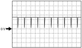
4.5 V or more (Maximum value of wave pattern)0.8 V or less (Minimum value of wave pattern)
-
CRANKSHAFT POSITION (CKP) SENSOR INSPECTION [SKYACTIV-G 1.5, SKYACTIV-G 2.0]
id0140g8800500
Visual Inspection
1. Disconnect the negative battery terminal. (See NEGATIVE BATTERY TERMINAL DISCONNECTION/CONNECTION.)
2. Lift up the vehicle.
3. Remove the front crossmember under cover. (See FRONT CROSSMEMBER UNDER COVER REMOVAL/INSTALLATION.)
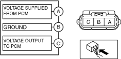
4. Disconnect the CKP sensor connector.
5. Remove the bolt. (See CRANKSHAFT POSITION (CKP) SENSOR REMOVAL/INSTALLATION [SKYACTIV-G 1.5, SKYACTIV-G 2.0].)
6. Remove the CKP sensor. (See CRANKSHAFT POSITION (CKP) SENSOR REMOVAL/INSTALLATION [SKYACTIV-G 1.5, SKYACTIV-G 2.0].)
7. Verify that there are no metal shavings on the sensor.
Voltage Inspection
1. Idle the engine.
2. Measure the CKP sensor output voltage wave pattern using an oscilloscope.
amxzzw00005539
|
Wave pattern (reference)
aaxjjw00014248
|