|
amxuuw00003379
FRONT WHEEL ALIGNMENT
id021100800200
Specification (Unloaded Condition)
|
Item |
Specification |
||
|---|---|---|---|
|
Total toe-in
|
Tire [Tolerance ±4 {0.2}]
|
(mm {in})
|
1.6 {0.063}
|
|
Rim inner [Tolerance ±2.8 {0.11}]
|
1.1 {0.043}
|
||
|
degree
|
0°09′±10′
|
||
|
Steering angle [Tolerance ±3°]
|
Inner
|
37°42′
|
|
|
Outer
|
32°06′
|
||
|
Steering axis inclination (Reference value)
|
13°53′
|
||
|
Camber
[Tolerance ±1°]
|
Vehicle height: From the end of the front fender to the center of the wheel (mm {in})
|
350—358 {13.8—14.0}
|
-0°30′
|
|
359—367 {14.2—14.4}
|
-0°18′
|
||
|
368—376 {14.5—14.8}
|
-0°07′
|
||
|
377—385 {14.9—15.1}
|
0°02′
|
||
|
386—394 {15.2—15.5}
|
0°08′
|
||
|
Caster
[Tolerance ±1°]
|
Vehicle height: From the end of the rear fender to the center of the wheel (mm {in})
|
350—358 {13.8—14.0}
|
8°18′
|
|
359—367 {14.2—14.4}
|
8°04′
|
||
|
368—376 {14.5—14.8}
|
7°51′
|
||
|
377—385 {14.9—15.1}
|
7°38′
|
||
|
386—394 {15.2—15.5}
|
7°24′
|
||
Steering Angle Adjustment
1. Loosen the tie-rod end locknuts.
2. Remove the steering gear boot clamp.
3. Rotate the tie rod and adjust the steering angle.
4. Rotate the tie rod and adjust so that dimension L shown in the figure does not exceed the specification.
amxuuw00003379
|
5. Tighten the tie-rod end locknuts.
6. Verify that the boot does not have any twisting and install the boot clamp.
7. After steering angle adjustment, always inspect and adjust the total toe-in. (See Total Toe-in Adjustment.)
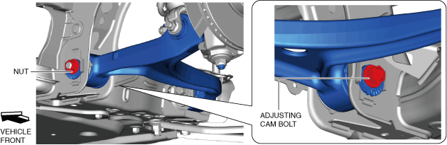
Camber Adjustment
1. Loosen the installation nut of the adjusting cam bolt on the front side of the front lower arm.
amxzzw00004432
|
2. Rotate the adjusting cam bolt in either direction to adjust the camber.
Specification
|
Vehicle height* |
Camber |
|---|---|
|
350—358 {13.8—14.0}
|
-0°30′±1°
|
|
359—367 {14.2—14.4}
|
-0°18′±1°
|
|
368—376 {14.5—14.8}
|
-0°07′±1°
|
|
377—385 {14.9—15.1}
|
0°02′±1°
|
|
386—394 {15.2—15.5}
|
0°08′±1°
|
|
|
Left wheel |
Right wheel |
|---|---|---|
|
Positive direction
|
Clockwise
|
Counterclockwise
|
|
Negative direction
|
Counterclockwise
|
Clockwise
|
Adjustment table of adjusting cam bolt on front side of front lower arm
|
Scale |
Link movement (mm {in}) |
Camber change amount (angle) |
|---|---|---|
|
1
|
1.2 mm {0.047 in}
|
-0°23′
|
|
2
|
2.3 mm {0.091 in}
|
-0°45′
|
|
3
|
3.2 mm {0.13 in}
|
-1°03′
|
|
4
|
3.9 mm {0.15 in}
|
-1°18′
|
|
5
|
4.3 mm {0.17 in}
|
-1°27′
|
|
6
|
4.5 mm {0.18 in}
|
-1°30′
|
3. Tighten the nut.
4. Adjust the front caster angle and total toe-in. (See Caster Adjustment.) (See Total Toe-in Adjustment.)
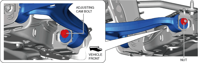
Caster Adjustment
1. Loosen the installation nut of the adjusting cam bolt on the rear side of the front lower arm.
amxzzw00004433
|
2. Rotate the adjusting cam bolt in either direction to adjust the caster.
Specification
|
Vehicle height* |
Caster |
|---|---|
|
350—358 {13.8—14.0}
|
8°18′±1°
|
|
359—367 {14.2—14.4}
|
8°04′±1°
|
|
368—376 {14.5—14.8}
|
7°51′±1°
|
|
377—385 {14.9—15.1}
|
7°38′±1°
|
|
386—394 {15.2—15.5}
|
7°24′±1°
|
|
|
Left wheel |
Right wheel |
|---|---|---|
|
Increase
|
Clockwise
|
Counterclockwise
|
|
Decrease
|
Counterclockwise
|
Clockwise
|
Adjustment table of adjusting cam bolt on rear side of front lower arm
|
Scale |
Link movement (mm {in}) |
Caster change amount (angle) |
|---|---|---|
|
1
|
1.9 mm {0.075 in}
|
0°34′
|
|
2
|
3.8 mm {0.15 in}
|
1°05′
|
|
3
|
5.3 mm {0.21 in}
|
1°32′
|
|
4
|
6.5 mm {0.26 in}
|
1°53′
|
|
5
|
7.2 mm {0.28 in}
|
2°06′
|
|
6
|
7.5 mm {0.30 in}
|
2°11′
|
3. Tighten the nut.
4. Adjust the total toe-in. (See Total Toe-in Adjustment.)
Total Toe-in Adjustment
1. Loosen the locknut of the tie-rod end.
2. Remove the boot clamp.
3. Adjust the total toe-in by rotating each tie rod (left and right) in the opposite directions by the same amount respectively.
4. Tighten the locknut of the tie-rod end.
5. Verify that the boot does not have any twisting and install the boot clamp.